Progress and Prospect of Infrared Imaging Optical System
- Share
- Issue Time
- Apr 23,2022
Summary
With the development of infrared focal plane detection technology, new requirements have been put forward for the design of infrared imaging optical systems and the processing of optical components. This paper briefly describes the progress and prospects of three generations of infrared imaging optical systems.
The infrared imaging optical system is an important link to achieving high-quality infrared/thermal imaging. Compared with visible light imaging optical systems, infrared imaging optical systems are more complex and difficult. The wavelength of infrared radiation is an order of magnitude larger than that of visible light and is prone to diffraction; the refractive index of infrared optical materials is large and there are few types, and the selection range of optical aberration correction with different material combinations is small; Therefore, the design and processing requirements of infrared imaging optical system and element surface shape are higher.
The radiant energy in the infrared band differs from that in the visible light band by several orders of magnitude. In order to obtain enough infrared radiant energy, the infrared/thermal imaging system needs to use a large aperture imaging optical system. For scenes with a distance (such as 5000m), an optical system with a long focal length (such as 200mm) is needed. In order to control the diffraction of infrared radiation, the relative aperture of the infrared imaging optical system needs to take a larger value (for example, the F-number is 1~4), the F-number of a typical visible light camera lens ranges from 1 to 22.
The development of the first generation of thermal imaging technology has produced infrared optical systems based on optical-mechanical scanning imaging, especially long-wave infrared optical systems based on germanium material optical elements.
The development of the second-generation infrared/thermal imaging technology has not only created new demands for infrared imaging optical systems from mid-wave infrared and short-wave infrared imagers but also created new demands for infrared imaging optical systems from uncooled thermal imagers. New infrared optical materials, design, and processing methods of infrared optical components are developed, which enriches the content of infrared imaging optical systems.
At present, infrared detectors are developing towards the third generation of infrared focal plane detectors. The size of the pixel exceeds one million pixels; the size of the detection element is reduced to 8um or even 5um; the thermal sensitivity is increased to the mK level, and the acquired information dimension increases the spectral dimension. (dual/multi-band), polarization dimension (4 polarization states), etc.
The new features of the third-generation infrared focal plane detector technology lead to the fact that the technology of the second-generation infrared imaging optical system cannot well meet, or even fail to meet the imaging requirements of the third-generation infrared/thermal imaging system. In other words, the third-generation infrared focal plane detectors put forward new requirements for the infrared optical system used in the third-generation infrared/thermal imaging system.
In this paper, the first- and second-generation infrared imaging optical systems are briefly reviewed. On this basis, the new problems to be solved by the third-generation infrared imaging optical system are sorted out, and the technical approaches and progress of the third-generation infrared imaging optical system to solve these new problems are reviewed. Finally, the development trend of the third-generation infrared imaging optical system prospects.
1. Problems existing in the first generation infrared imaging optical system
In the first-generation thermal imaging system, due to the large scanning angle of the scanning beam, the aperture diaphragm of the optical system is generally set before the scanning mirror/device, and the aperture diaphragm is relatively large. When the infrared radiation flux density of the target (such as a long-distance target) is lower than the infrared radiation flux density of the infrared imaging optical system (including infrared optical components, supporting structures, etc.), the infrared radiation generated by the infrared imaging optical system is regarded as the main background noise. The astigmatism is received by the infrared detector to form a "daffodil effect" image superimposed on the thermal image of the scene, which has become an important factor limiting the thermal sensitivity of the first-generation thermal imaging system and affecting the thermal image quality.
Problems with the first generation of infrared imaging optical systems:
1) The infrared imaging optical system needs to be customized; the structure is complex; the transfer function is low; the number of optical components is large, and the system installation and adjustment requirements are high;
2) Effective integration with infrared detectors cannot be achieved, and the size and weight of the infrared imaging optical system are relatively large;
3) The "daffodil effect" of the refractive infrared imaging optical system is more serious.
2. Features of the second-generation infrared imaging optical system
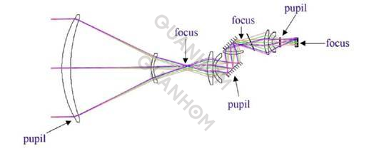
To overcome the influence of the "daffodil effect", the second-generation infrared imaging optical system strengthens the cold screen design, increases the cold screen efficiency to 100%, and minimizes the influence of background stray light; the second imaging mode is adopted to reduce the effect the entrance pupil diameter and the volume of the infrared objective lens. The cold diaphragm is set at the exit pupil to minimize the aperture of the diaphragm and block most of the stray light (Figure 1), which improves the image quality.
In the subdivision application of infrared/thermal imaging system, the second-generation infrared imaging optical system has the following technical characteristics:
1) The thermalization technology has been developed to reduce the defocusing of the optical system due to temperature changes.
2) Hybrid optical elements and aspherical optical elements are developed for diffraction surface processing of refractive element, diffraction surface corrects the axial color difference and chromosphere difference, aspherical surface, and lens can eliminate both spherical difference and wisdom difference, improve the imaging quality, and simplify the optical system.
3) The application of long focal length and long-distance infrared/thermal imaging system develops the axial reflection infrared optical system, and the axial size of the system is reduced by folding the optical path, such as the axial reflective Cassegrain optical system. Due to the large occlusion of the axial reflection system, the effective incident radiation is reduced, and an off-axis reflection system without occlusion, such as an off-axis three-mirror infrared optical system, has been developed. To avoid new occlusions caused by too many mirrors, a refractive optical system is usually set behind the mirrors to focus the infrared radiation on the infrared focal plane detector. In 2011, Min Wang et al. of the National Institute of Optics of Canada designed a four-channel common aperture total reflection off-axis infrared telescope, with four bands of 3.4um~4.0um, 8.3um~9.3um, 10.0um~11.0um and 11.5um -12.5um, and the detector is a 256×1 linear infrared focal plane detector.
4) A wide variety of uncooled infrared optical systems have been developed for the application of lightweight and miniaturized uncooled thermal imagers such as thermal sights and individual thermal imagers.
5) A standardized, universalized and serialized replaceable, the fixed-focus single-field infrared optical system has been developed to meet the application requirements of high quality, large scale, and low cost.
6) The optical-mechanical-integrated dual-field, three-field, and large zoom ratio continuous zoom infrared optical system has been developed for high-performance military applications.
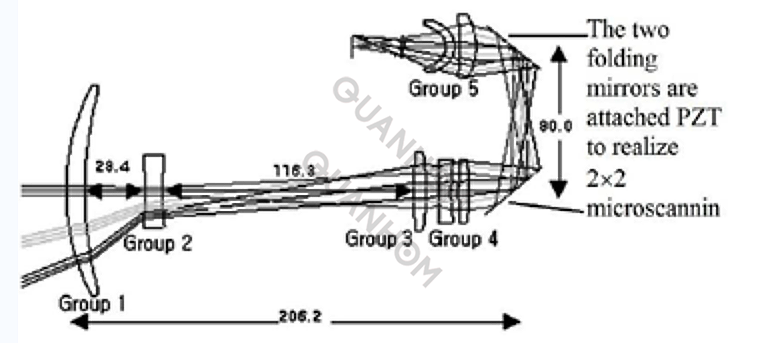
7) Facing diversified application requirements, it develops a lightweight, high-performance, and compact optical system integrating various technical advantages. For example, in 2002, Hyun Sook Kim et al. designed a 20: continuous mid-wave infrared optical system with 1 variable ratio and 22 micro scannings. In addition to reducing the system size, two mirrors can also perform upper, lower, and left and right pendulum sweeps respectively, so as to achieve 22 micro scanning imaging. The system is compact, with a length of only 206.2mm, a height of 80mm, a weight of 5.3kg, a working band of 3.7um to 4.8um, an F-number of 2.5, and a zoom range of 12.75mm to 275mm, as shown in Figure 2.
3 Research status of the third-generation infrared imaging optical system
The third-generation infrared focal plane detector puts forward new requirements for the infrared imaging optical system. The specific analysis is as follows:
1) Under the condition that the volume of the infrared optical system remains unchanged, the operating distance and sensitivity of the infrared/thermal imaging system are optimized at the same time.
The fixed cold screen F-number of the second-generation cooled infrared focal plane detector makes it possible to obtain 100% cold screen efficiency with only one optical system F-number. The simplified mathematical expressions for the range and sensitivity (NETD) are:
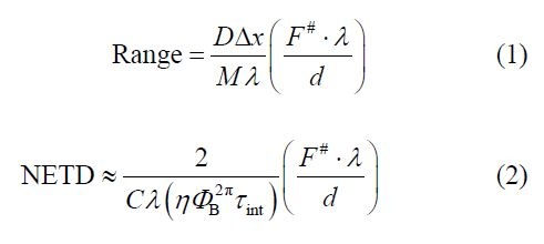
where D is the entrance pupil diameter; F# is the F-number; λ is the wavelength; M is the number of pixels required to confirm the target Δx; C is the scene contrast; d is the size of the detector element; η is the detector collection efficiency; ΦB2π represents Background radiant flux for a 2π field of view; τint is the integration time.
It can be seen from formula (1) that keeping the volume of the infrared optical system unchanged means fixing the entrance pupil diameter D, then the larger the F#, the larger the working distance, but the sensitivity NETD decreases with the increase of F, which indicates that in the second-generation optical system a single F# in the system cannot meet the requirements of range and sensitivity at the same time. Therefore, the third-generation infrared optical system is firstly designed with a variable F-number, so as to optimize simultaneously the working distance and sensitivity of the infrared/thermal imaging system.
2) Under the condition of minimizing the number of lenses and maximizing the transmittance of the optical system, it can achieve clear imaging in the mid-wave infrared and long-wave infrared bands and dual-band pixel-level fusion imaging at the same time.
The feature of the dual-band infrared focal plane detector using the stacked pixel structure is that the pixel size and pixel scale of the dual-band are the same, and the independent readout circuits read out the dual-band data respectively. The issues that need to be considered when designing the infrared optical system of the dual-band infrared focal plane detector are as follows:
Dual-band infrared radiation of the same scene should be focused on the same focal plane detector without refocusing, and sufficiently high image quality should be obtained;
The double band reaches the diffraction limit at each field of view
The focal length of the dual bands should be the same;
Distortion should be the same for both bands;
Chromatic aberration caused by the difference in the dispersion of infrared optical materials in the mid-wave and long-wave infrared bands should be corrected.
In response to these problems, the dual-band third-generation infrared optical system greatly simplifies the field of view registration of the two bands by adopting a common aperture design. At the same time, a catadioptric optical system with a wide spectrum, small chromatic aberration, small axial size, and flexible design is adopted. In addition, a dual-band "picture-in-picture" infrared optical system has been developed.
3) Reducing the volume, weight, power consumption, and cost of infrared/thermal imaging systems is an eternal requirement: "there is no best, only better".
In response to this requirement, the third generation of infrared optical systems has developed micro-optical systems, free-form optical systems, etc.
4) Infrared optical systems for computational imaging, the potential of optical systems should be fully exploited through intelligent computing.
In response to this requirement, optical multiplex imaging has been developed. Brief descriptions are given below.
3.1 Development of variable F-number cooling infrared imaging optical system
The variable F-number infrared imaging optical system can give full play to the advantages of the third-generation infrared detectors with high sensitivity and high spatial resolution (large area array), and optimize the spatial resolution and sensitivity of the system while maintaining the volume of the original thermal imaging system, improve the signal-to-noise ratio when searching for a target with a wide field of view, and maintain the ability to point to and track the target at a long distance (i.e. when the field of view is narrow). For the limited entrance pupil diameter in practical applications, choose a large F-number in a narrow field of view, and focus on the action distance; choose a small F-number in a wide field of view, and focus on the field of view and sensitivity. For multi-band detectors, choose a large F-number for the mid-wave infrared band, and a small F-number for the long-wave infrared band.
3.2 Development of catadioptric infrared imaging optical system
According to the characteristics of the catadioptric infrared optical system with a wide spectrum, small chromatic aberration, small axial size, and flexible design, the infrared imaging with common aperture, double F-number, dual/multi-band, multi-field/large zoom ratio continuous zoom has been developed. The optical system meets the requirements of integrated and automated target search, confirmation, and tracking of weapon platforms with limited installation space.
3.3 Development of dual-band "picture-in-picture" infrared imaging optical system
A dual-band "picture-in-picture" infrared imaging optical system is developed to simultaneously search and identify targets through spatial information and spectral information of different optical magnifications on one screen.
For common ground object scenes, the medium-wave and long-wave infrared images output by the medium-wave/long-wave infrared dual-band focal plane detector have a high degree of correlation (that is, there is no obvious difference between the images), and the operator needs to zoom repeatedly between the wide field of view and narrow field of view to search and identify objects of interest. In order to make full use of the ability of dual-band focal plane detectors to synchronously obtain information in separate bands, and to take advantage of the fact that the peak radiation wavelength of ground objects is located in the long-wave infrared band and the contrast of medium-wave infrared images is high, the dual-band “picture-in-picture” infrared imaging optical system has been developed in recent years. It uses wide-field long-wave infrared images to perceive the situation of ground objects and scenes, and narrow-field medium-wave infrared images to obtain high-contrast target images.
3.4 Development of a catadioptric peripheral infrared imaging optical system
According to the advantage of the large scale of the third-generation infrared focal plane detection pixels, a catadioptric circular infrared imaging optical system based on quadratic surface mirrors was developed, and a single infrared focal plane detector was used to record a wide field of view and even a 360°circumference view Field information to meet the needs of infrared warning and alarm.
3.5 Development of free-form surface infrared imaging optical system
With the support of advanced optical manufacturing and measurement technology, free-form surface infrared imaging optical systems are developed to overcome the difficulties such as widening the field of view, correcting aberrations, simplifying the structure of optical systems, controlling volume, and reducing weight.
Freeform surfaces provide complex geometries that are not rotationally symmetric, enabling unconventional image acquisition and aberration correction. In 2014, Kyle Fuerschbach of the University of Rochester, Jannick P. Rolland, and Kevin P. Thompson pointed out that the free-form surface can be completely described using the existing aberration theory. This study found that optical designers can break the limitation of rotational symmetry, and design free surfaces of any shape according to the current mathematical models, to obtain a completely unobstructed infrared optical system, completely composed of reflective optical elements. The three researchers also designed and verified a fully reflective infrared optical system using only three free surfaces, with diffraction limit as low as 5um, F-number 1.9, high compactness, high thermal stability, and lightweight diagonal field of view 10, which can be installed in a complex three-dimensional space without a folding mirror.
3.6 Development of miniature uncooled infrared imaging optical system
Ultra-thin, miniature uncooled infrared imaging optical systems were developed to meet high-performance infrared imaging requirements under the constraints of volume, weight, and power consumption (SWaP).
With the substantial reduction in the volume and weight of uncooled infrared focal plane detector components, the demand for miniature infrared imaging optical systems with optical path lengths less than 1/2 of the focal length is increasing. Low-cost, simple processed spherical reflectors are widely used for folding optical paths, refractive optical elements are also used to reduce the occlusion of the reflection surface to the optical path.
4. Outlook
The infrared imaging optical system is extending from the objective lens to the infrared focal plane detector chip and its signal processing circuit by reducing its size. When the size of the optical element unit is reduced to the same size as the detector, operations such as spectrum, polarization, and phase encoding at the pixel level can be realized. For example, the "infrared retina" proposed by Sanjay Krishna in 2009 regards each pixel of the infrared detector as a cone cell in the retina, and couples the interactions between these cells through later information processing technology, thereby imitating the human eye’s function of perceiving scene information and recognizing the situation of the scene; when the optical element unit is further reduced to the micrometer or nanometer scale, due to the surface effect, volume effect and quantum size effect, its optical performance will show characteristics significantly different from the macroscopic optical element unit, such as superior absorption, antireflection or convergence properties. It can be said that the development trend of infrared optical systems is to integrate with infrared detectors, and nanophotonics has become the driving force for the development of the fourth generation of infrared focal plane detectors.
QUANHOM is a professional custom infrared lenses and components manufacturer. Our team bridges the gap between superior performance and limited budget, especially when we are involved in projects integrating high precision. Products include infrared optical assemblies for VIS/SWIR/MWIR/LWIR, eyepieces, infrared lens elements (from monoscopic to Quickly switching between multi-field and continuous zoom infrared lenses), etc. If you need, please contact us.