Infrared Zoom Lens System for Target Detection
- Share
- Issue Time
- Mar 25,2022
Summary
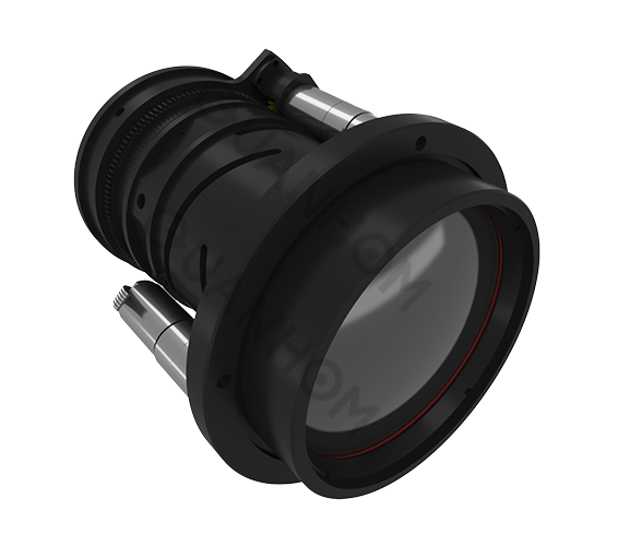
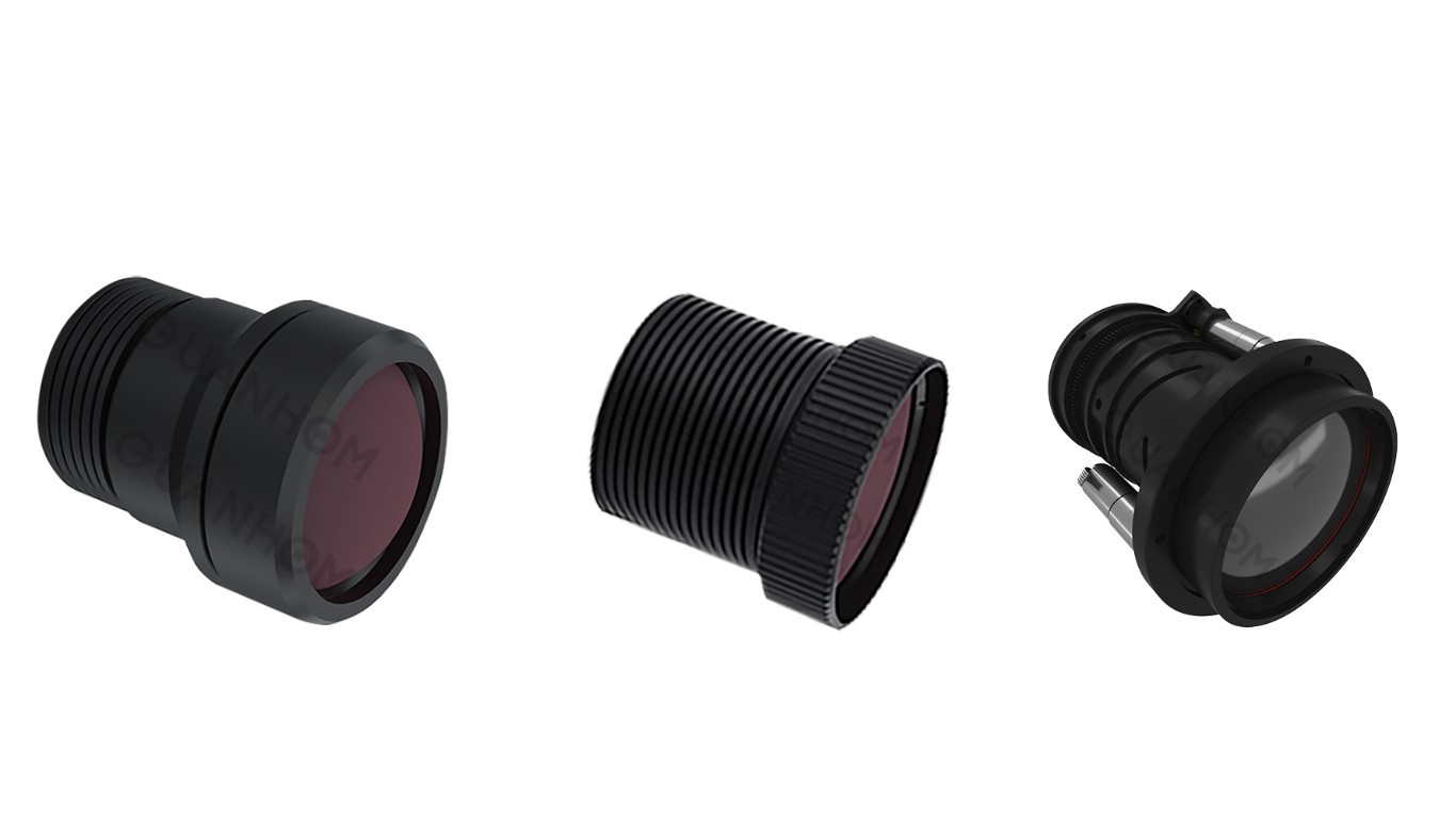
This article describes an infrared (IR) zoom lens gadget designed to detect missile signatures at 8 to 13 Bin wavelengths.

1.6.Computer optimization
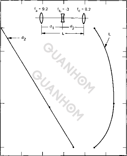
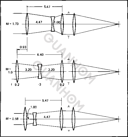
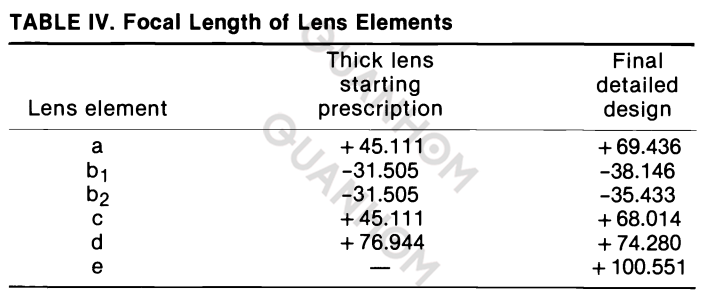
An evaluation of optical layout applications for infrared-type optical systems has been provided at a previous SPIE technical symposium.10 David grey's pc application is particularly nicely proper for zoom lens programs. His optimization program for robotically compensated zoom lenses (MZOOM) changed into applied for the exact design of this zoom lens. It's far a completely powerful application that optimizes for 9 specific positions throughout the zoom variety concurrently at the same time as maintaining a fixed photo plane over the complete variety. The consumer can input boundary situations to govern such parameters as allowable vignetting, lens thickness, and normal machine duration. The thickness and spacing bounds for the unit focal period device used by grey in optimization are shown in Table III. The dimensions factor in millimeters to the significant system is 109.98, the focal duration of the enter prescription. The tabulation of starting and final lens detail focal lengths presented in table IV suggests that the optimization software was allowed to depart from the starting afocal first-order properties to locate the exceptional solution to the problem. This could also be seen from a comparison of the beginning and final unitized lens separations shown in Figs. Four(a) and four(b). The general period of the afocal element has been allowed to increase by 19.0 mm to achieve higher stability of the aberration residuals over the zoom range. It most effectively took some distinctly cheaper runs from beginning to finish to optimize the machine.
2. Conclusions
This paper has described a simple however powerful zoom lens optical gadget for the IR that offers 1 mrad decision for all conditions of use. This zoom lens is useful for goal detection over a huge set of operating conditions due to the fact the picture plane is usually in consciousness over the entire zoom range. Tolerance issues were presented for preserving sharp consciousness because the zoom components flow to trade the magnification.
The method of the optical layout manner has additionally been provided. The position of the computer has been set forth as a powerful computational device that serves to supplement the conceptual and analytic abilities which the designer brings to his assignment.
Quanhom's is a professional custom infrared optics manufacturer of LWIR lenses, MWIR lenses, thermal imaging cameras, and system component manufacturer. From simple infrared lens element subassemblies to sophisticated and reliable complex optomechanical and electro-optical assemblies. Not only do we provide basic products, but we are also committed to providing comprehensive customization services. Our one-stop solutions to complex challenges in defense, security, and commercial applications are recognized by customers worldwide. Through innovative design, custom engineering, optical system evaluation, and fabrication, our multilingual team (English, Spanish, Italian, and Russian) ensure seamless communication from project inception to completion. From consulting to final production, nearly 60 projects are carried out each year. Quanhom's talented team has created many success stories for different applications such as thermal imaging sights for outdoor and defense use, thermal imaging monoculars/binoculars, border, and coastal security, maritime applications, and UAV infrared payloads.
3. References
1. Woehl, W. E., Opt. Eng. 20(3), 450 (1981).
2.Altman, R. M. and Rosenblatt, J. J. of Hughes Aircraft Company, Zoom Lens Optical System for Infrared Wavelengths, U.S. Patent No. 3,825,315 (23 July 1974).
Noyes, G. R. of Hughes Aircraft Company, Long-Wave Infrared Afocal Zoom Telescope, U.S. Patent No. 3,947,084 (30 March 1976). Noyes, G. R., Proc. SPIE 131, 24 (1978).
Jamieson, T. H., Opt. Acta 18(1), 17 (1971).
Cox, A., A System of Optical Design, p. 463, Focal Press, (1964).
Kingslake, R., Journal of the SMPTE 69, 534 (1969).
Welford, W. T., Aberrations of the Symmetrical Optical System, p. 141, Academic Press, (1974).
Riedl, M. J., Electro-Optical Systems Design, 58 (November 1974). Juergens, R. C. and Mann, A., Proc. SPIE 131, 28 (1978).
David Grey Associates Computer Optics Package (COP) MZOOM Reference Manual for Mechanically Compensated Zoom Lenses, Genesee Computer Center, Inc., Rochester, New York (June 1980).
Smith, W. J., Modern Optical Engineering, p. 426, McGraw-Hill, New York (1966).