Design of Airborne Miniaturized Middle Wavelength Infrared Continuous Zoom Optical System
- Share
- Issue Time
- Mar 18,2022
Summary
In order to meet the requirements of the airborne photoelectric system for the miniaturization and light weight of the infrared thermal imager optical system, this paper adopts the combination of the front-end afocal expansion magnification lens and the rear-end continuous zoom optical system to achieve 22x continuous zoom from 30 to 660mm. optical system.
Infrared imaging is completed by the infrared radiation radiated by the object itself after passing through the imaging system, and the thermal radiation is related to the temperature of the object. Therefore, infrared imaging can achieve all-day imaging during the day and night, and has the ability of all-weather target detection and identification.
In addition, because it belongs to passive imaging, it has the advantage of not being easily interfered and has strong camouflage identification capabilities. Infrared imaging systems are installed in airborne optoelectronic systems of air vehicles such as helicopters, fixed-wing aircraft, and UAVs to help complete combat missions such as battlefield situational awareness, target search, target tracking, target detection and identification, and effect assessment of weapon guidance and strike. In short, infrared imaging systems have become one of the standard configurations of optoelectronic systems.
The fixed-focus infrared imaging optical system has a fixed focal length, which makes it difficult to meet the detection and identification requirements of targets at different distances. The continuous zoom infrared optical system has a large field of view in the short-focus state, and its imaging receiving area is large; in the long-focus state, the field of view is small, and its imaging resolution is high. Applied in the airborne optoelectronic system, the large field of view can be used for a wide range of target search, and the small field of view can be used for detailed inspection and identification, tracking, and aiming of the target.
In addition, since the continuous zoom imaging system always maintains a clear image of the target when the focal length is changed, when tracking or aiming the target, the focal length can be adjusted according to the observation needs of selecting the appropriate observation field of view. During the process of switching the field of view, the stable tracking of the target can be maintained without missing, thereby effectively improving the ergonomic design.
In this paper, the combination of the front-end afocal magnification lens and the rear-end continuous zoom optical system is adopted. After adding the magnification lens, a 22x continuous zoom optical system of 30-660mm is realized. The rear-end continuous zoom optical system can realize a 22x continuous zoom optical system from 15 to 330 mm after removing the front-end afocal magnification lens.
1. Design indicators
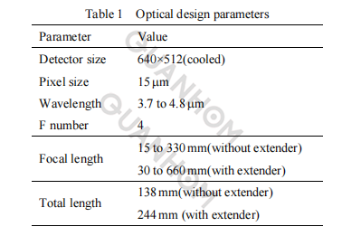
In this paper, a continuous zoom optical system is designed for the widely used 640×512 element-cooled infrared detector. The pixel size of the detector is 15μm×15μm, and the response band is 3.7-4.8μm. The design parameters of the optical system are shown in Table 1.
2. Design ideas
Figure 1 shows the composition of the optical system. The front-end afocal expansion magnification lens and the rear-end continuous zoom optical system are combined. The two parts are designed independently. The rear-end continuous zoom optical system adopts a three-component mechanical compensation structure, thus effectively shortening the length of the optical system and realizing a miniaturized design.
The front end is a 2x afocal telescope, which is used to expand the focal length of the optical system. In the design, the exit pupil of the front telephoto system and the entrance pupil of the rear continuous zoom system match each other. The front-end magnification lens doubles the focal length of the rear-end continuous zoom optical system to achieve long focus, which is suitable for large-scale airborne optoelectronic pod systems for long-distance target detection.
After removing the front afocal expansion lens, the rear continuous zoom optical system can be used as an independent continuous zoom system in the small and medium-sized airborne optoelectronic pod system for short-range target detection.
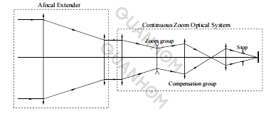
Fig.1 Continuous zoom optical system composition
Figure 2 is the optical schematic diagram of the rear-end continuous zoom system, in which 1 is the front fixed group, 2 is the zoom group, 3 is the compensation group, and 4 is the rear fixed group.
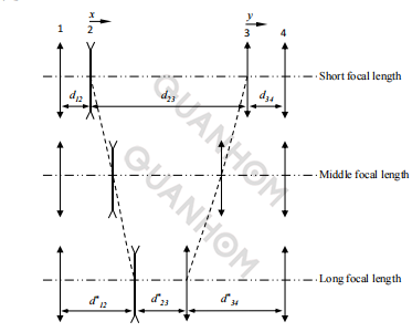
Fig.2 Schematic diagram of mechanically compensated zoom system
The zoom ratio of the system is:

In the formula: β2 and β3 are the initial magnifications of the second and third components respectively; β*2 and β*3 are the magnifications of the second and third components after the zoom movement.
The initial magnifications of the zoom group and the compensation group are:
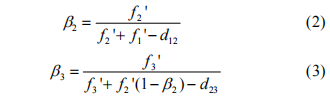
In the formula: f1’, f2’, f3’ are the focal lengths of the first, second, and third components respectively; d12 is the initial interval between the first and second components; d23 is the initial interval between the second and third components.
The magnifications of the zoom group and the compensation group after the zoom movement are as follows:

In the above formula:
The amount of movement of the compensation group:

The intervals between the components are:

First give normalized initial values: d12, d23, f2’=-1, f3’, β3=-1√M to calculate the initial structure of the system.
Taking the short focal length as the starting position, the normalized value is given: f2’=-1. During the design, the focal length of the compensation group should not be too long or too short. If it is too long, the required compensatory quantity of the compensation image plane will be too much, which goes against the realization of miniaturization design. If it is too short, the relative aperture undertaken by the compensation group will be too large, which make aberration correction more difficult. The focal length of compensation group is generally about 3 times of the focal length of zoom group, and f3’=3.
When the focus is the shortest, the distance between the zoom group and the front fixed group is the closest, so the selection of d12 should ensure that the lenses do not touch each other and leave some margin, and take d12=0.5. Assuming d23=6 at short focus, according to formulas (1) to (9), the system is in long focus state: d* 12=7.3, d* 23=0.6, and the focal lengths of each component are f1’=11, f2’=-1, f3’=3.
3. Design results and image quality evaluation
3.1 Design results
The mechanical positive group compensation continuous zoom optical structure model is used, and the optical design software is used for optimization after the initial model is established and zoomed. Due to the large short-focus field of view of the system, both off-axis aberrations and high-order aberrations are relatively large. For the correction of high-order aberration, the design introduces high-order aspheric and diffractive surfaces to better balance off-axis and on-axis aberrations.
With the secondary imaging structure, the entrance pupil of the system is closer to the front lens group, so the projection of the chief ray of the off-axis field of view on the front lens group is lower, thereby reducing the aperture of the front lens.
In addition, in the design of the optical-mechanical structure, a field diaphragm is set at the position of the primary image plane, so that the stray light outside the system's field of view cannot pass through the field diaphragm to reach the image plane, which can effectively reduce the influence of stray light on the imaging of the optical system , which improves the signal-to-noise ratio.
The aperture diaphragm is set at the exit pupil of the optical system. The aperture diaphragm is the same as the cold diaphragm of the cooling detector. Thus, the F number of the system is the same as that of the detector, achieving 100% cold diaphragm efficiency. Hence, there will be no energy loss caused by beam cutting; therefore, the system sensitivity is improved.
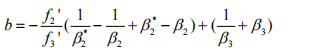
The final design of the optical system is shown in Figures 3 to 6. After adding the expansion lens, it can realize the 22x continuous zoom function with the focal length changing continuously in the range of 30 to 660mm. The total optical length of the system is 244mm, and the total length / maximum focal length ratio is 0.37, so it has the characteristics of small total optical length and large zoom ratio.
After removing the front afocal extender, the rear continuous zoom optical system can realize 22 times continuous zoom function with the focal length continuously changing in the range of 15-330mm. The total optical length of the continuous zoom optical system is 138mm, and the total length/maximum focal length ratio is 0.42. The total length of the system is short, and the volume is small.
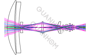
Fig.3 Optical system layout at 15mm
Fig.4 Optical system layout at 330mm
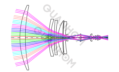
Fig.5 Optical system layout with extender at 30mm
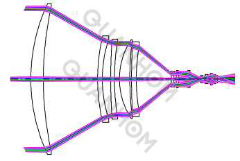
Fig.6 Optical system layout with extender at 660mm
3.2 Image quality evaluation
For the imaging optical system, the optical modulation transfer function (MTF) is the ratio of the modulation degree of the image to the modulation degree of the object. It is a function of the spatial frequency and can express the change of the contrast of the target background after passing through the imaging system at each frequency component.
The high-frequency, intermediate-frequency and low-frequency parts reflect respectively the detail transfer, level transfer and contour transfer of the object, which are the most comprehensive criteria of the performance of the imaging optical system.
Figures 7 and 8 are the MTF curves of the optical system in this paper when the short focus is 15mm and the long focus is 330mm without adding a magnifying lens. According to the figures, at the point where the 640×512 cooled detector has the characteristic frequency of 331p/mm, the MTF values of the central field of view are all around 0.3, which is close to the diffraction limit. The MTF values of the 0.7 field of view are all around 0.2, and the MTF values of the edge fields of view are all around 0.15. For the airborne imaging system, the main area observed by the human eye is within the 0.7 field of view of the image. Therefore, the optical system can meet the application requirements.
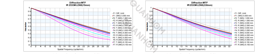
Fig.7 MTF graph with focal length of 15mm Fig.8 MTF graph with focal length of 330mm
Figure 9 and Figure 10 are the MTF curves of the optical system in this paper after adding the magnification lens when the short focus is 30mm and the long focus is 660mm. According to the figures, at the point where the characteristic frequency of the 640×512 cooled detector is 331p/mm, the MTF values of the central field of view are all around 0.3, which is close to the diffraction limit. The MTF values of the 0.7 field of view are all around 0.2, and the MTF values of the edge fields of view are all around 0.15, which can meet the application requirements.
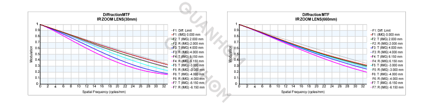
Fig.9 MTF graph with focal length of 30mm with extender Fig.10 MTF graph with focal length of 660mm with extender
In the imaging process of geometric optics, due to the aberration of the optical system, after the light emitted from a point on the object surface is imaged by the optical system, it is no longer concentrated at one point on the image plane, but forms within a certain range a geometric image pattern which is called a spot diagram.
The spot diagram provides the basis for image quality evaluation, and it is a convenient and easy method to use the spot diagram to evaluate the image quality of the optical system. The root means square (RMS) diameter of the scattered spot of the optical system is the diameter of a circle containing about 68% of the energy.
Figures 11 and 12 show the optical system in this paper without adding an expander, with a short focus of 15mm and a long focus of 330mm. It can be seen from the figures that the maximum RMS speckle diameter of the system is 20.9μm. The Airy disk diameter of the system is 2.44λ.F#=39.04μm; therefore, the diameter of the diffused spot is smaller than the diameter of the Airy disk, which meets the application requirements.
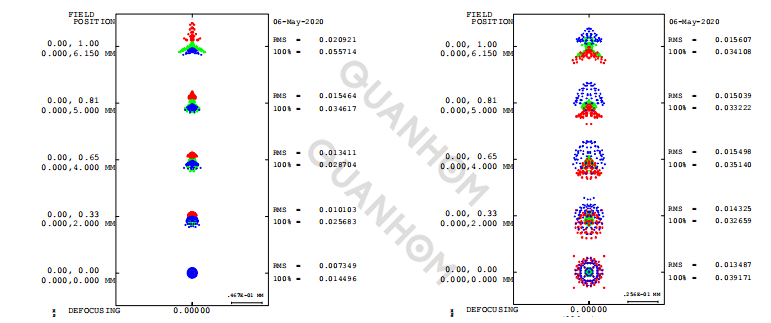
Fig.11 Spot diagram when the focal length is 15mm Fig.12 Spot diagram when the focal length is 330mm
Figure 13 and Figure 14 are the spot diagrams of the optical system in this paper after adding the expansion lens when the short focus is 30mm and the long focus is 660mm. It can be seen from the figures that the maximum RMS dispersion spot diameter of the optical system is 23.5μm, which is smaller than the Airy disk diameter of 39.04μm; thus it meets the application requirements.
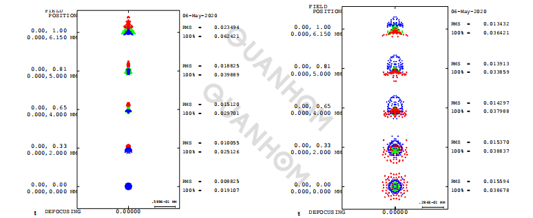
Fig.13 Spot diagram when the focal length is 30mm with extender Fig.14 Spot diagram when the focal length is 660mm with extender
In the structure of a continuous zoom lens, a zoom cam is usually used to drive the zoom group and the compensation group to move. The two lens groups of the zoom group and the compensation group are respectively mounted on two carriages, and a guide pin is fixed on each carriage and moves along the cam curve groove.
When the motor rotates to drive the cam to rotate, the guide pins of the two carriages move along their respective guide grooves, driving the zoom group and the compensation group to move along the optical axis in a predetermined relationship, thereby changing the focal length of the lens.
The mechanism has the advantages of stable transmission, simple control, reliability, zero bouncing, and small backlash. The zoom cam curve groove is processed by the zoom curve data in the CNC machine tool. Therefore, for the continuous zoom optical system, the fitting of the zoom curve is the key link between the optical design and the optical-mechanical structure design.
Figure 15 is the zoom motion curve diagram of the zooming optical system and the compensation group, in which the abscissa is the focal length of the optical system, and the ordinate is the distance between the zooming group and the compensation group from the front fixed group. It can be seen from the figure that the movement of the zoom group and the compensation group is smooth and continuous during the focal length change process, and there is no inflection point, which can effectively avoid the system stagnation during the zoom movement.
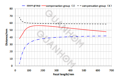
Fig.15 Zoom curves of continuous zoom subsystem
4. Conclusion
This paper adopts the combination of the front-end afocal extender and the rear-end continuous zoom optical system. After adding the extender, a 22x continuous zoom optical system from 30 to 660mm is realized. The total optical length of the system is 244mm, and the total length/maximum focal length ratio is is 0.37, so the system is compact in structure, and it has the characteristics of small total optical length and large zoom ratio, and is suitable for large-scale airborne photoelectric pod systems for long-distance target detection.
After removing the front afocal extender, the rear continuous zoom optical system can realize a 22x continuous zoom optical system from 15 to 330mm. The total optical length of the system is 138mm, and the total length/maximum focal length ratio is is 0.42. It can be used as an independent continuous zoom system for small and medium sized airborne photoelectric pod systems for short-distance target detection.
According to the different needs of mission equipment, the front-end expansion mirror can be added or removed to adapt to the volume and focal length requirements of different optoelectronic pods for the infrared continuous zoom system, thereby effectively shortening the system development cycle, reducing technical risks and development costs, expanding the scope of application of the product, and extending the life cycle of the product. In short, it has a good application prospect in airborne optoelectronics and other fields.
As a high-quality infrared lens supplier integrating the design, manufacture and sales of opto-mechanical components, Quanhom is committed to making users all over the world enjoy our high-quality services. We have a professional quality inspection department, which can control the quality of products in all aspects. We have the most advanced research and design team, and continuously introduce more infrared lens series. If you are interested in our infrared thermal imaging lenses, please contact us immediately!
Authors: Wu Haiqing, Wang Weichao
Journal source: Infrared Technology Vol.43 No.12 Dec. 2021
Received date: 2021-01-01; Revised date: 2021-11-25
References:
[1]WANG Lingxue, CAI Yi. Recent progress and perspectives of infrared optical systems [J]. Infrared Technology, 2019, 41(1): 1-10.
[2]JI Shupeng. Equipment development of airborne electro-optic payload and its key technologies[J]. Aero Weaponry, 2017(6): 3-12.
[3]HUANG Jun, ZHANG Zhengyong, TIAN Shengmin. Current status and development trend of airborne air to ground electro-optical detection equipment[J]. Infrared Technology, 2018, 40(5): 412-416.
[4]WANG Xiangjuna, WANG Min. A zoom system design suitable for miniaturization of UAV pod[J]. Opto-Electronic Engineering, 2013, 40(1): 139-144.
[5]XUE Hui, LI Changwei. Optical design of infrared continuous-zoom lenses[J]. J. Infrared Millim. Wawes, 2012, 31(5): 421-424.
[6]WU Haiqing, LI Tonghai, ZHAO Xinliang, et al. Design of large imaging plane middle wave infrared continuous zoom optical system[J]. Infrared, 2019, 40(1): 7-10.
[7] WANG Zhijiang. Practical Optical Technology Manual[M]. Beijing: China Machine Press, 2007: 429-430.