Design of a Long Wave Infrared Double-Linkage Continuous Zoom Optical System
- Share
- Issue Time
- Jan 20,2022
Summary
In this article, based on the 640×512 long-wave cooled infrared detector, which has been maturely applied, a dual-group linkage long-wave infrared continuous zoom optical system is designed.
Infrared thermal imaging systems are passive detection and do not require active auxiliary lighting. Therefore, they have been widely used in night vision navigation, incoming warning, target reconnaissance and other fields. For targets with high-temperature radiation sources such as aircraft, the external thermal radiation is concentrated in the mid-wave infrared band.
The mid-wave infrared thermal imaging system has advantages in the detection and identification of such targets; due to the low surface temperature of ground military targets such as buildings, their thermal radiation is concentrated in the long-wave infrared band, and the long-wave infrared system can suppress the adverse effect of sea surface sparkling on the target imaging.
Therefore, the long-wave infrared system has more advantages in target detection under adverse weather conditions such as low visibility and mist, as well as in the detection and identification of surface ship targets.
Due to diffraction effects, the Airy disk diameter of an optical system is proportional to the wavelength and F-number. For the long-wave infrared thermal imaging system, in order to improve its resolution, it is necessary to design an optical system with a large relative aperture. Therefore, it is of great significance to study optical systems with small F-numbers and large relative apertures.
The infrared continuous zoom system is realized by the axial movement of the zoom group and the compensation group. According to different compensation methods, it is divided into two forms: optical compensation and mechanical compensation.
In the optical compensation zoom system, since the moving group is responsible for the functions of zoom and compensation at the same time, it is difficult to achieve a large zoom ratio; for the mechanical compensation zoom system, the change interval between the zoom group, the compensation group, and the fixed group is small, The system is not easy to achieve large relative aperture and miniaturized design.
In this article, based on the 640×512 long-wave cooled infrared detector, which has been maturely applied, a dual-group linkage long-wave infrared continuous zoom optical system is designed. The zoom group of the system uses two fixed lens groups to perform linear or non-linear motion to achieve focal length change, and the compensation group performs nonlinear motion to compensate for the defocusing of the system image plane caused by the movement of the zoom group. Ensure that the image can always be clear during the zooming process.
Without increasing the difficulty of moving the component control system, the pressure angle of the cam curve of the zoom system can be reduced, the number of system lenses can be reduced, and the zoom ratio of the system can be improved while realizing a large relative aperture and miniaturization.
1. Principle of double-group linkage zoom and calculation of the initial structure
Figure 1 shows the optical principle diagram of the dual-group linkage zoom system. In the figure, 1 is the front fixed group; 2 and 4 are zoom groups, which are fixed together to perform linear motion (or non-linear motion) in the same direction; 3 is compensation group, located between the two zoom groups, performs non-linear motion to compensate for the defocusing of the system image plane caused by the movement of the zoom group, so as to ensure that the image plane of the system remains stable during the zooming process; 5 is the rear fixed group.
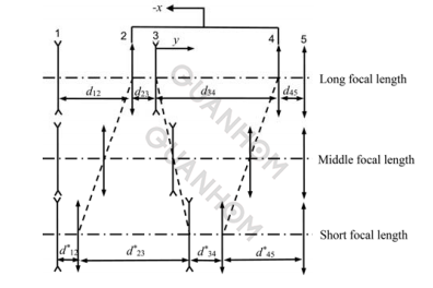
Fig.1 Sketch map of the double-linkage zoom system
The zoom ratio of the system is:
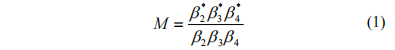
In the formula: β2, β3, β4 are the initial magnification of the 2nd, 3rd, and 4th components, respectively, β*2, β*3, β*4 are the 2nd, 3rd, and 4th components after the zoom movement magnification. The initial magnifications of the zoom group and the compensation group are:
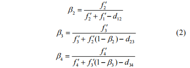
In the formula: f1, f2, f3, f4 are the focal lengths of the 1st, 2nd, 3rd and 4th components respectively, d12 is the initial interval between the 1st and 2nd components, and d23 is the distance between the 2nd and 3rd components. The initial interval between d34 is the initial interval between the 3rd and 4th components.
The magnifications of the zoom group and the compensation group are:
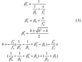
The amount of movement of the zoom group:

The amount of movement of the compensation group:

The interval between the components is:

First, give normalized initial values: f3, d23, d34, take β3=-1, β2, β4=1 or β2=-1, β3=1, β4=1 to calculate the initial structure of the system.
2. Design indicators and design results
2.1 Design Indicators
Detector: 640×512 refrigeration;
Pixel size: 15μm;
Working band: 7.7μm~9.5μm;
F-number: 2.24;
Focal length: 30 mm ~ 360 mm;
System diameter: ≤180 mm;
The overall length of the system: ≤320 mm.
2.2 Design results and image quality analysis
Set the telephoto as the starting position, take the normalized value: f3=1, d23 is the shortest at the telephoto, and it is enough to ensure that the lenses do not touch each other, take 0.05, set the telephoto as d34=1.5, take β3 =-1, β2β4=1 Carry out the calculation of the initial structure of the system. Substitute into formulas (1) to (9) to get the system in the short focus state: d12*=0.2, d23*=1.5, d34*=0.02, d45*=0.9; in the long focus state: d12=0.9, d23=0.3 , d34=1.5, d45=0.2, the focal length of each component is: f2=-0.35, f1=1.5, f4=-6.
After scaling the obtained initial structure, the optical design software was used for adjustment and optimization. Finally, a dual-group linkage optical system suitable for a 640×512 long-wave cooled detector was designed as shown in Fig. 2.
The system F-number was 2.24, and the working band was Longwave 7.7 μm~9.5 μm, composed of 8 lenses, the maximum diameter is 166 mm. The third lens is made of ZnSe material, and the rest are all made of Ge material, of which the back surface of the first lens and the back surface of the third lens are aspherical. A schematic diagram of the zooming process of the continuous zoom optical system is shown in Figure 3.
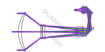
Fig.2 Structure of optical system
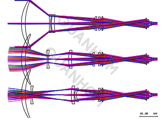
Fig.3 Zoom process diagram of optical system
Figure 4, Figure 5, and Figure 6 are the modulation transfer function curves of the system at short, medium and long focal lengths. The pixel size of the 640×512 long-wave cooled infrared detector is 15μm, and the corresponding characteristic frequency is 33lp/mm, the transfer function of the optical system in the 0.7 field of view is close to the diffraction limit, and the value of the transfer function in the edge field of view is greater than 0.15, which meets the application requirements.
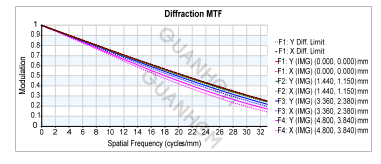
Fig.4 MTF curves of short focal length

Fig.5 MTF curves of middle focal length
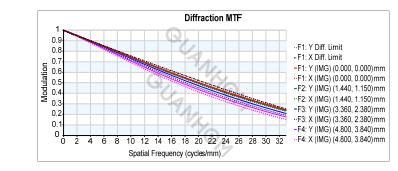
Fig.6 MTF curves of long focal length
Figure 7, Figure 8, and Figure 9 are the spot diagrams of the system at short, medium, and long focal lengths. It can be seen from the figures that the diameter of the dispersion spot of the system at different focal lengths is smaller than the theoretical diameter of the Airy disc of the system, to meet the application requirements.
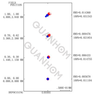
Fig.7 Spot diagram of short focal length
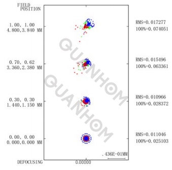
Fig.8 Spot diagram of middle focal length
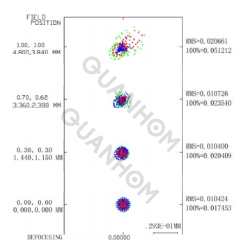
Fig.9 Spot diagram of long focal length
Figure 10, Figure 11, and Figure 12 are the field curvature and distortion curves of the system at short, medium and long focal lengths. It can be seen from the figures that the distortion of the system under different focal lengths is less than 2.5%, which meets the application requirements.
Figure 13 is the zoom curve diagram of the continuous zoom optical system, the abscissa is the focal length of the continuous zoom optical system, and the ordinate is the axial distance of the zoom group and the compensation group relative to the front fixed group. It can be seen from the figure that the zoom curve of the system is smooth and continuous, and there is no sudden change, which can effectively avoid the system stuck in the zoom process.
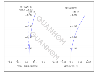
Fig.10 Astigmatic field curves and distortion of short focal length
Since the zoom group is composed of two groups of lenses, which share the optical power of the zoom group, the pressure angle of the cam curve of the zoom group can be reduced. Before the simulation analysis of the cam structure, it is necessary to optimize the cam curve.
When optimizing the cam curve, it is necessary to ensure that the zooming process is uniform and stable. At the same time, for the convenience of processing, the pressure angle of the cam curve cannot be too large, and the maximum cannot exceed 45°.
Fig. 14 is a graph of the pressure angle of the zoom cam of the continuous zoom optical system. The system adopts the non-linear motion of both the zoom group and the compensation group. After optimization, the maximum pressure angle of the zoom curve is 41.31°, the maximum pressure angle of the compensation curve is 34.29°, and the cam circumference angle is 172.45°.
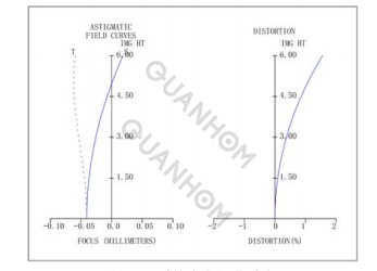
Fig.11 Astigmatic field curves and distortion of middle focal length
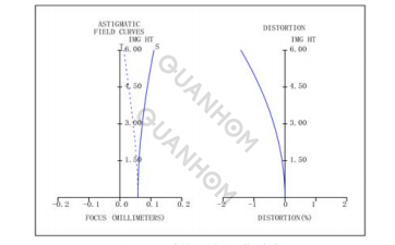
Fig.12 Astigmatic field curves and distortion of long focal length
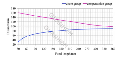
Fig.13 Zoom curves of continuous zoom optic system
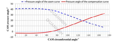
Fig.14 Zoom cam pressure angle of continuous zoom optic system
3. Conclusion
In this paper, the design of a dual-group linkage infrared optical system is studied. Based on a 640×512, 15μm long-wave cooled infrared detector, a dual-group linkage long-wave infrared continuous zoom optical system with a focal length of 30mm to 360mm and an F-number of 2.24 is designed.
The zoom group of the system is made of two fixed lens groups to perform the linear or non-linear motion, and the compensation group performs nonlinear motion to compensate for the defocusing of the system image plane caused by the movement of the zoom group, thereby ensuring that during the zooming process able to image sharply at all times. The results show that the pressure angle of the cam curve can be reduced, and the design of a large relative aperture and miniaturization can be achieved without increasing the difficulty of the moving component control system.
We are an experienced manufacturer of Opto-electromechanical components, dedicated to providing users with a variety of high-quality infrared thermal imaging lenses. We take the needs of customers as the first priority and comprehensively control the quality of our products. For this reason, we are equipped with a strict quality inspection system to control the design, manufacturing, and export of the products. If you are interested in our infrared thermal imaging lens, please contact us immediately!
Authors: Wu Haiqing, Zhao Xinliang, Li Tonghai, Tian Haixia, Cui Li
Journal source: Infrared Technology Vol.41 No.7 July 2019
Received date: 2018-12-18; Revised date: 2019-06-26.
References:
[1] LUO Shoujun, XIA Yinhui, YANG Ningning, et al. Long-wavelength infrared continuous zoom scanning optical system[J]. Chinese Optics, 2015, 8(1): 107-113.
[2]LI Ruiyao, FU Yuegang, LIU Zhiying. Athermalization Design of Compact Medium-wave Infrared Imaging System[J]. Infrared Technology, 2018, 40(2): 119-124.
[3] HE Wubin, HAO Junming, WU Wei, et al. Design of long-wavelength low F/# continuously zooming infrared optical system[J]. Laser & Infrared, 2013, 43(7): 757-760.
[4] WANG Zhijiang. Practical Optical Technology Manual[M]. Beijing: China Machine Press, 2007: 429-430.