Design of Three-field Middle-wave Infrared Zoom System
- Share
- Issue Time
- Dec 10,2021
Summary
By reading this article, you can fully understand the design scheme of the mid-wave infrared three-field zoom optical system. Quanhom has designed a three-field zoom optical system that works in the mid-wave spectrum.
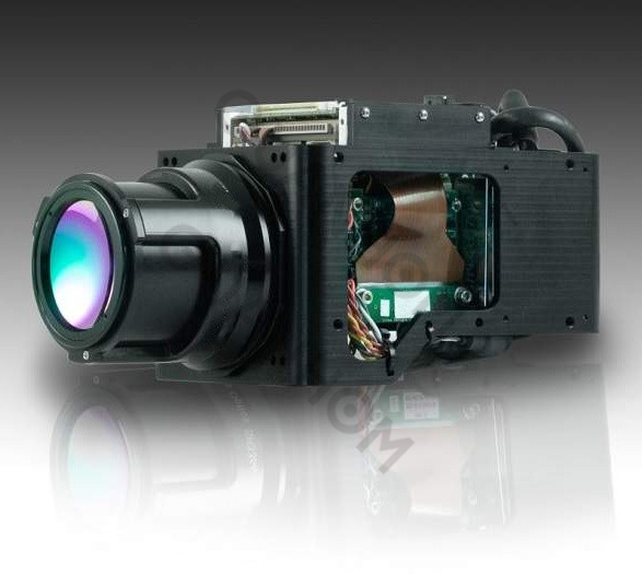
Three-field zoom system has advantages of simple mechanical structure, better reliability, short time of changing focal relative to other pattern zoom systems. Using a 320×240 resolution cooled detector with 30μm×30μm pixel dimension, a middle-wave three-field optical system was designed by secondary imaging way. The system's F-number is 4, the FOV range is 1.4°-23.8°, it can realize 30 mm/100mm/500mm three-position focal length.
In the designing process, the Germanium material and Silicon material were adopted to balance chromatic aberration, introducing one asphere to balance sphere aberration. The system uses two mirrors reducing the axis dimension. The dimension of the system is better than 210mm×160mm×120mm, it has characteristics of small dimension, simple zoom structure, good image quality, etc. The modulation transfer function (MTF) is above 0.5 at a spatial frequency of 17lp/mm and the energy concentration ratio is greater than 70% within the sensing element of the detector.
In recent years, with the development of infrared processing and semiconductor industries, infrared systems have become more and more widely used. Because the infrared system has some characteristics that the visible light system does not have, such as night imaging, non-contact temperature measurement, etc., infrared imaging is increasingly used in night rescue, night surveillance, and other fields.
With the development of infrared system application requirements, the shortcomings of the fixed focus system are becoming more and more obvious. It has a single field of view and cannot achieve a large field of view general survey and a small field of view detailed inspection. The zoom system can just make up for this deficiency.
Compared with the continuous zoom system, the three-field zoom system can eliminate the need for complex cam curve design. Through simple mechanical compensation, three different focal lengths of the long, medium, and short can be realized, corresponding to the three types of narrow, medium, and wide. For different fields of view, the corresponding field of view or focal length can be selected according to different use occasions.
Compared with the traditional zoom system, the three-field zoom system has the advantages of less visual axis shake and shorter zoom time. In this paper, a cooled detector with a resolution of 320×240 and a pixel size of 30μm× 30μm is used to design a three-field zoom optical system working in the mid-wave spectrum.
The system F-number is 4, the telephoto focal length is 500 mm, and the focal length is 100 mm, the short focal length is 30 mm, and the field of view angles are 1.4°, 6.8°, and 23.8° respectively. The system consists of 9 lenses and two mirrors, meeting 100% cold diaphragm efficiency, compact structure, and good image quality, and other characteristics.
1. Design parameters and discussion
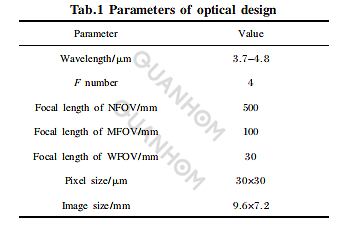
Using a 320×256 resolution refrigerated detector, the design parameters of the optical system are shown in Table 1.
Since the system is a refrigerated infrared optical system, how to reduce the cold reflection of the system is an important consideration in the design. Cold reflection is a common phenomenon in refrigerated infrared systems. Different from the visible light system, in the infrared system, each frame or barrel is a radiation source, which is reflected by the non-working surface of the optical part and enters the infrared detector.
If the distribution of this full field of view is not uniform, grayscale gradients will be generated during imaging. In most cases, the grayscale at the center is lower than the grayscale at the edges, and the imaging system will appear black in the center and bright at the edges. It can be considered as background noise, which is superimposed on the target image during imaging. When the cold reflection is severe, it can seriously affect the image quality. Therefore, it is necessary to focus on the analysis and evaluation of the cold reflection effect during the design.
2. System design process and design result analysis
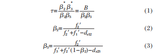
The system adopts the structure of single zoom group and single compensation group, and its Gaussian solution should satisfy the following equation:
Zoom group displacement:

Compensation group displacement:

The interval between the zoom group and the fixed group after zooming:

The interval between the zoom group and the compensation group:

It can be known from the geometrical optics object image relation formula:

The conjugate distance of the system is:

In the above formula: T is the zoom ratio of the system; β2 is the vertical magnification of the initial position of the variable magnification group; β3 is the vertical magnification of the initial position of the compensation group;β*2 is the vertical magnification of the variable magnification group after zooming magnification; β*3 is the vertical axis magnification of the compensation group after zooming; f1' is the focal length of the front fixed group; f2' is the focal length of the variable magnification; f3' is the focal length of the compensation group; ds12 is the initial position of the variable magnification group as the previous fixed group Interval; ds23 is the interval between the zoom group and the compensation group; d*s12 is the interval between the zoom group after zooming and the previous fixed group; d*s23 is the interval between the zoom group and the compensation group after zooming.
Substituting formulas (8) and (9) into formula (10), we can get:

Substitute the obtained β*2 into the above formulas to calculate the basic parameters of the optical system. By changing the position of the zoom group and the compensation group to change the combined magnification, the system can switch between different focal lengths. In actual use, the focal length can be selected according to the size and distance of the target, and the focal length can be quickly switched to the specified position according to the need to shorten the zoom time. The movement trend of the negative group zoom system is shown in Figure 1.
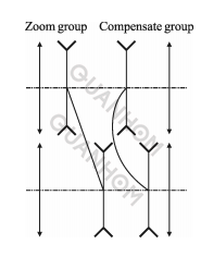
Fig.1 Principle diagram of the optical system
In the design, the diaphragm of the optical system is placed at the cold screen position of the detector, and the second imaging method is used to achieve 100% cold diaphragm efficiency. According to the relevant formula, the diaphragm position at different focal length structures of the system can be calculated to ensure different focal lengths. The position can satisfy 100% cold aperture efficiency.
In order to reduce the axial size of the system, the system adopts a negative group compensation zoom method without object image exchange. It can be known from related references that when the focal length of the compensation group |f3′| is too large, the total length of the system will increase, so in the system, the size of |f3′| is limited during optimization.
The final normalized focal length of the compensation group of the system is |f3'|=1.3. When the focal length of the compensation group decreases, the relative aperture of the compensation group will increase, which will increase the difficulty of system aberration correction.
The design uses an aspheric surface to correct the spherical aberration and coma aberration, and the aspheric surface is added to the sixth negative lens of germanium material in the system. The germanium material with a large dispersion coefficient in the medium wave band is used as the negative lens, and the silicon material with a small dispersion coefficient in the medium wave band is used as the positive lens so that the system can ensure good imaging quality at each zoom position. The design result is shown in Figure 2.
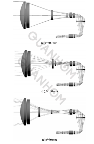
Fig.2 Optical schematic of design
By changing the positions of lens 3 and lens 4, the system realizes long, medium, and short focal lengths, eliminating the need for cam curve design and reducing the complexity of the system. Before the light path is refracted, the length of the system is 400mm, and the telephoto ratio (total length/focal length)=400/500=0.8. After the light path is refracted by the mirror, the overall size of the system is less than 210mm×160mm×120mm. The system has a compact structure and meets the requirements of miniaturization.
The optical transfer function characterizes the imaging ability of the lens to targets of different spatial levels, among which, the low frequency characterizes the contour, the intermediate frequency characterizes the level, and the high frequency characterizes the resolution ability. In general imaging systems, the transfer function is greater than 0.2, and the transfer function of the infrared lens is generally required to be greater than 0.4.
A spherical aberration correction system is introduced in the design, located in the sixth lens, the pixel size of the system is 30μm, the Nyquist frequency is 16.7lp/mm, and the three focal lengths of the system are at 17lp/mm, the transfer function curve is shown in Figure 3.
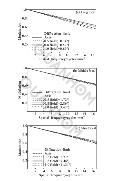
Fig.3 Curves of MTF
It can be seen from the figure that the transfer function values of the system are all greater than 0.5, which is close to the diffraction limit, indicating that the system has good imaging quality and high resolution. Figure 4 shows the energy curve of the diffraction encircling circle of the system. It can be seen from the figure that about 70% of the energy is concentrated in the detector's sensitive element, which meets the basic requirements of infrared refrigeration detection.
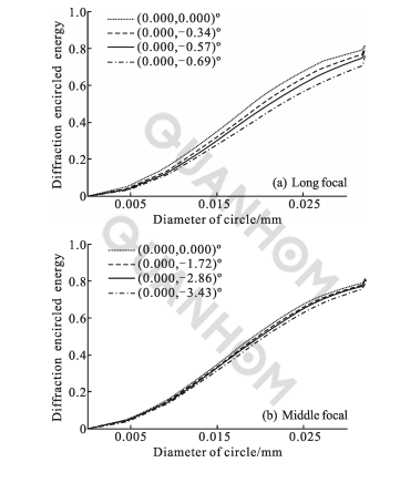
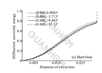
Fig.4 Diffractive spot
3. Cold reflection analysis
Because the cold diaphragm of the refrigerated detector can reflect through the refraction surface in the front optical system, it can receive cold radiation from itself and the surrounding environment to form a cold reflection image. The cold reflection will form a dark spot in the center of the target surface, making the system's signal noise-ratio is reduced, so it must be considered in the design to minimize its impact on the system's imaging.
In order to suppress cold reflection, commonly used methods are:
(1) Anti-reflective coating is applied to improve the transmittance of optical elements and reduce the reflectivity to reduce the energy involved in the reflected imaging beam;
(2) Control the angle of the reflected imaging light to avoid incidents along the normal direction of the surface as much as possible. The incident light along the surface normal is easy to reflect the target surface of the detector.
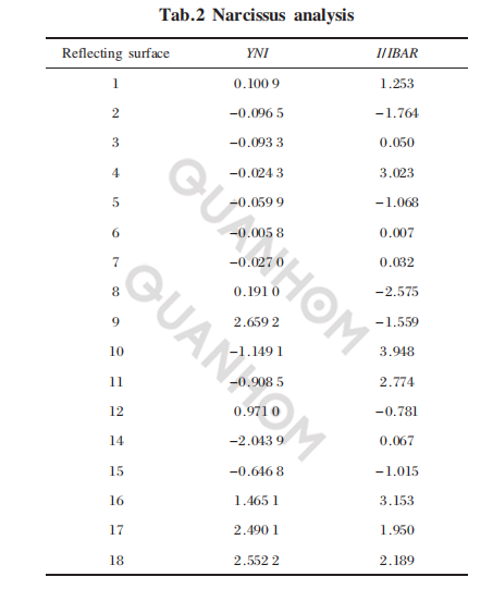
In cold reflection analysis, YNI and I/IBAR are important parameters for investigation, where Y is the height of the edge ray, N is the surface refractive index, I is the incident angle corresponding to the edge ray Y, and IBAR is the incident angle of the chief ray. Usually when YNI≥1, it indicates that the contribution of this face to cold reflection can be ignored. When the YNI value is small and I/IBAR<1, the surface may produce a severe cold reflection.
The analysis shows that the system may have severe cold reflections at short focus. Table 2 shows the analysis results of the system's short focus positions. From the table, it can be seen that the cold reflections on surfaces 3, 6, and 7 may be more serious. Since the YNI value and I/IBAR value of surface 6 are the smallest, focus on the sixth surface.
Turn the system upside down, use the detector as the light source, trace the light backward, and set the 6th surface of the system as the reflective surface for ray tracing. Figure 5 shows the result of ray tracing. It can be seen from the figure that the image formed by the light from the image plane reflected by the surface 6 is far away from the image plane, and the cold reflection effect caused by it can be ignored.
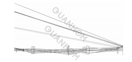
Fig.5 Schematic diagram of cold reflection ray-tracing
4. Conclusion
The article introduces the characteristics of the three-field zoom optical system in detail, and uses a 320×240 resolution refrigerated infrared detector to design a mid-wave infrared three-field zoom optical system with three focal lengths of 30mm,100mm and 500 mm, the design process and design results are given.
In the design, two materials are used to correct the chromatic aberration of the system, and the spherical aberration of the system is corrected by the aspheric surface, which improves the imaging quality of the system. The secondary imaging method is used to make the system reach 100% cold diaphragm efficiency. The total length of the system's optical path before turning is 400 mm, and the telephoto ratio reaches 0.8. After two mirrors are used to turn the optical path, the total length is less than 210mm.
The transfer function curve of the system is close to the diffraction limit, and the energy concentration of the enclosing circle is high, indicating that the system has good imaging quality. At the end of the article, the cold reflection is analyzed, and the cold reflection analysis method and analysis results are given. The analysis results show that the cold reflection influence can be ignored. The system is small in size, compact in structure, meets miniaturization requirements, and can be widely used in airborne search camps and rescue night imaging.
The infrared optical lens designed and manufactured by Quanhom has the significant advantages of lightweight and high resolution and can be effectively monitored in a variety of complex and harsh environments. If you want to get further related services, you can send us your needs, and we will give you a satisfactory answer as soon as possible.
As an experienced manufacturer of Opto-electromechanical components, Quanhom is equipped with a professional quality inspection system and a comprehensive management team and enjoys a high reputation in the industry. Our products are sold all over the world and are used in all walks of life. Our thoughtful one-stop shopping service has also received unanimous praise from customers. If you are interested in our infrared optical lenses, please contact us immediately!
Authors: Fan Zheyuan, Gao Limin, Zhang Zhi, Chen Weining, Yang Hongtao, Zhang Jian, Wu Li, Cao Jianzhong
Journal source: Vol.43 No.2 Infrared and Laser Engineering Feb.2014
Manuscript received: 2013-06-14; revision date: 2013-07-19
References:
[1] Zhang Mingyi, Li Baoping, Wang Zhongnan, et al. Design of the switch-zoom dual-field-of-view infrared optical system with hybrid refractive-diffractive [J]. Infrared and Laser Engineering, 2008, 37(5): 850-853. (in Chinese)
[2] Chen Lvji, Chen Jinjin, Li Ping. A novel stop-zoom LW infrared dual field-of-view optical system design[J]. Infrared Technology, 2011, 33(7): 406-410. (in Chinese)
[3] Zhao Xinliang, Wang Haixia, Cui Li, et al. Design of dual- field scanning LWIR optical system [J]. Infrared and Laser Engineering, 2011, 40(8): 1517-1520. (in Chinese)
[4] Dong Keyan, Sun Qiang, Li Yongda, et al. Design of a refractive/diffractive hybrid infrared bifocal optical system[J]. Acta Physica Sinica, 2006, 55(9): 4602-4606. (in Chinese)
[5] Luo Shoujun, He Wubin, Li Wenhu, et al. Design of middle infrared continuous zoom optical system with a large FPA [J]. Optics and Precision Engineering, 2012, 20(10): 2117- 2122. (in Chinese)
[6] Zhou Hao, Liu Ying, Sun Qiang. Mid-infrared zoom optical system with ratio of 25[J]. Acta Optica Sinica, 2012, 32(4): 0422001-1-0422005. (in Chinese)
[7] Tao Chunkan. Zoom Lens Design [M]. Beijing: Beijing National Defense Industry Press, 1988: 33-39, 140-153. (in Chinese)
[8] Fan Zheyuan, Yang Hongtao, Qu Enshi, et al. Design of long-wave infrared scan system with large field and large aperture [J]. Infrared and Laser Engineering, 2012, 41(10): 2740-2744. (in Chinese)