Design of Compact High Zoom Ratio Infrared Optical System
- Share
- Issue Time
- Nov 26,2021
Summary
In view of the various problems of commonly used zoom structures in realizing large-scale continuous zooming, Quanhom shared the corresponding zoom equations and optimized control conditions and methods for cam curve design.
Aiming at various problems existing in commonly used zoom structures when realizing large-scale continuous zooming. Starting from the basic theory of zoom system design, a two-stage series variable magnification model that can be used in the design of a large variable ratio optical system is proposed, and the corresponding zoom equation and optimal control conditions and methods for cam curve design are given.
The model is composed of a two-element continuous zoom front group and a secondary imaging rear group with variable magnification function in series. The first zoom group and compensation group in the front group are moved; the compensation group and the second zoom group are moved.
The secondary zooming group in the imaging group performs secondary magnification on the focal length of the front group to expand the zooming capability of the entire imaging system. At the same time, the secondary imaging group also compresses the aperture of the objective lens to ensure the matching of the cold stop.
Completed the design of a large variable ratio continuous zoom optical system. The working band of the system is 3.7~4.8μm. It adopts 640x480 cooling area array detector, the pixel size is 15um, the F number is constant at 4, and it can achieve 6.5-455mm, horizontal viewing angle. The continuous zoom function of 0.92°-58.2°, up to 70 times, uses only two materials, ten lenses, and a total length of 300mm. It has excellent imaging quality and tolerance characteristics.
The upper limit of the zoom of the two-element zoom optical system is about 50 times. If it exceeds this value. During the axial movement of the zoom group, the change of the angle of light on the lens surface will cause large aberrations, which is difficult.
Correction: the use of three-component or more component linkage structure can achieve a greater zoom ratio, but in the multi-group linkage system design, the elimination of zoom breeding points and the design and processing of complex cam curves are realized by engineering Bring greater difficulties. At the same time, the multi-group linkage method also reduces the reliability of the entire imaging system.
In addition, the zoom ratio of the infrared continuous zoom optical system, which is widely used in recent days, is about 30 times. There are common problems such as large zoom stroke and long field of view switching time. It is difficult to control the visual axis jump during zooming, which greatly restricts This kind of equipment is widely used.
In response to the above problems, the paper adopts the design idea of two-stage zoom based on the design theory of zoom system, and expounds the realization of a compact and large zoom continuous zoom optical system, which can be used as a reference for the design of similar large zoom systems.
1. Design basis
In order to facilitate the discussion, the paper uses the thin lens theory to describe the involved models.
1.1 Two-stage series zoom design model
Figure 1 shows a schematic diagram of a two-stage series zoom design model. The entire optical system is composed of a two-element continuous zoom front group and a secondary imaging rear group with variable magnification function in series.
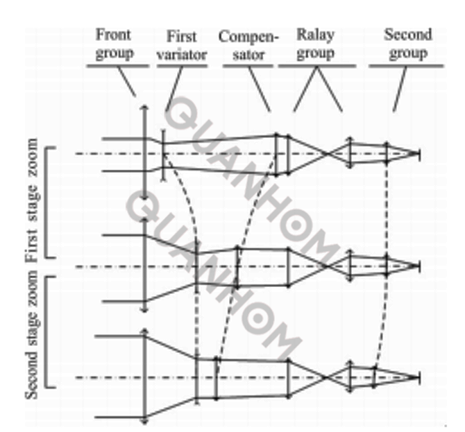
Fig.1 Schematics of two-stage-of-series zoom lens design model
The front group adopts the traditional two-element zoom structure to realize the first-level zoom of the optical system: the entire first-level zoom process, only the two moving groups of the zoom group and the compensation group participate, and the traditional cam sleeve mechanism can be used. Meet the structural design requirements to ensure the feasibility of the system.
When zooming to a certain position, the zoom group stops moving, and the optical system shifts to the second zoom: the compensation group and the second zoom group are designed according to the design good regular movement to achieve secondary zoom in the focal length of the front group.
At this time. Through proper processing, the movement curve of each dynamic group can be smoothly transitioned with the curve in the first-stage zooming process, made on the same cam sleeve mechanism. The difficulty of processing and control is reduced; the movement of the second-stage zooming group can be It is restricted by a separate cam sleeve or lead screw guide mechanism, and has the function of focusing the entire optical system through a suitable control mechanism.
Therefore, through the two-stage series zooming method, each stage of the zooming process has only two moving components, which improves the aberration correction capability of the entire optical system, avoids imaging blind spots in the zooming process, and simplifies the design of the cam curve The process provides great convenience for the realization of the optical-mechanical structure.
1.2 Zoom equation and parameter solution
The method of zoom differential equation is used to describe the design model of two stages in series to achieve large zoom ratio. In the design model, the compensation group participates in the whole process of the first and second stages of zooming, and the zoom group and the second stage zooming group participate in the first and second zooming processes respectively.
Therefore, in the design process of the cam curve, take the compensation group as the active group, the zoom group and the secondary zoom group as the driven group, and set the focal length of the zoom group as f'2,the magnification ratio m2, and the axial movement as △2 ; the focal length of the compensation group is after f'3, the magnification is m3, and the axial movement is △3; the focal length of the secondary zoom group is f'4, and the magnification is m4.
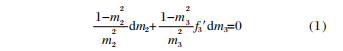
For the first-level zoom process, it is realized through the linkage of the zoom group and the compensation group, that is:
The compensation group is the active group, and the change of the magnification m3 is caused by the change of the object distance, that is:

The zoom group is the driven group, and the change of the magnification m2 is caused by the change of the object distance, that is:

In the same way, for the secondary zooming process, it is realized through the linkage of the compensation group and the secondary zooming group, that is:
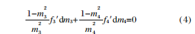
Given the initial conditions, using multiple methods to solve equations (1) and (4), the optical power distribution of each component and the corresponding zoom can be obtained under the conditions of first-stage and second-stage variable magnification.
The movement curve, and the movement curve of each component is solved in sections, which guarantees the continuity of the curve, and will not be repeated here. However, the segmented solution cannot guarantee the switching time of the two-stage zoom, and the smooth transition of the motion curve needs to be considered separately.
Take the smoothing of the two sections of the zooming curve (including the first-level zooming motion curve and the second-level zooming static straight line) as an example. In order to ensure the smooth transition of the curve, it is required that the slopes of the two sections of the curve at the time of switching the zoom level are equal, that is:

Substituting formula (2) into formula (1) can be obtained:

Organize to get:
Where: m22 ≠0. If you want to make it, m33 -1=0, and considering that m3=1 is meaningless, it can be seen that taking m3=-1 can ensure the smooth transition of the two-level zoom group during the two-level zoom switch.
The same can be proved: when m3=-1,
At this time, the smooth transition of the two-level zoom can be guaranteed when the two-level zoom is switched.
In addition, in order to ensure the smoothness of the curve, it is necessary to ensure the first-level zooming process. The motion curves of the zooming group and the compensation group are smooth and continuous, that is, it is necessary to ensure that at the moment m3=-1, the zooming group magnification |m2|< 1.
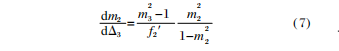
If the short focal position is taken as the starting point, the magnification ratios of the zoom group and the compensation group at the short focal position are set to m2s and m3s, and the formula (1) is solved by integration, and the zoom group magnification can be obtained:
Formula:
Substituting m3=-1 into formula (8), the magnification m2 of the variable magnification group at the time of switching of the variable magnification order can be obtained. At this time, if m2<-1 is found, the value can be modified by m3s or m2s make adjustments to satisfy |m2|≤1.
2. Design example
A design example is selected to discuss and explain the above method. The design example uses the 3.7~4.8μm mid-infrared refrigerated focal plane detector, the image element is 640×480, the pixel size is 15μm×15μm, and the diagonal length is 12mm. The specific design indicators are shown in Table 1.

The primary variable magnification structure of the optical system adopts the form of positive group compensation; the front fixed group with positive optical power is a monolithic structure, using silicon material with weak dispersion ability to assume the main optical power; taking into account the large zoom ratio,the system’s long and short focal position aberrations are balanced, and the variable magnification group with negative refractive power also uses silicon with weak dispersion capability.
This ensures that during the entire movement of the zoom group, it will not introduce too much chromatic aberration at the short focal position, and compress the incident angle of the light on the surface of the rear group, reducing the pressure of the rear group aberration correction.
The compensation group adopts a typical three-piece structure composed of silicon-germanium-silicon according to the positive-negative-positive optical power distribution, and independently corrects the chromatic aberration, spherical aberration, coma, etc. of the lens group.
The middle fixed lens group mainly functions, the function of the field lens is to compress the beam width and reduce the volume of the secondary imaging lens group; the secondary zoom lens group has a positive refractive power, adopts a two-piece structure, is a combination of two materials of silicon and germanium, and also eliminates the mirror independently. Primary aberrations within the group.
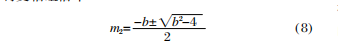
Using Code V software to optimize and analyze the above optical system, Figure 2 shows the optimization results of the compact and large zoom ratio mid-infrared continuous zoom optical system and the corresponding MTF evaluation. The system only uses two infrared materials, silicon and germanium, and a total of 10 lenses.
The total length of the optical system from the surface of the optical system close to the object side to the focal plane is 300mm, the maximum diameter of the single lens is less than 112mm, and the maximum distortion rate of the zoom is less than 5%.
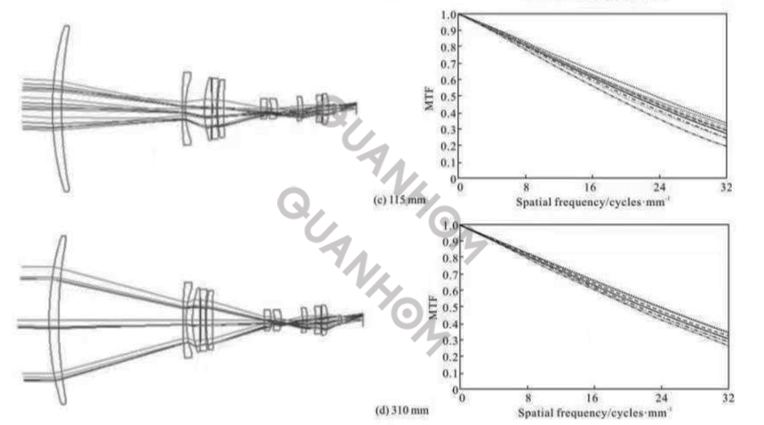
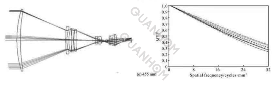
Fig.2 Design result and corresponding MTF performance of the compact high zoom ratio MWIR optical system
The cut-off frequency of the designed optical system at each focal length position is 33 1p/mm, and the central field of view MTF is greater than 0.28. The transfer function of each field of view has a good distribution, which indicates that the system has good imaging quality, which proves The feasibility of the above design method.
Use the compiled macro program to optimize the cam curve design of the completed compact large zoom ratio mid-infrared continuous zoom optical system. Figure 3 is a schematic diagram of the optimized zoom system cam curve. It can be seen that the entire zoom system zoom compensation process Smooth without inflection point.
In addition, the reflectivity of each surface is 0.01, the average temperature of the optical-mechanical structure is 20°C, the background temperature of the detection scene is 20°C, the temperature inside the detector Dewar is -195.86°°C, and the Narcissus Induced Temperature Difference (NITD) is adopted. The evaluation of the cold reflection characteristics of the above-mentioned zoom system shows that the entire optical system at the short focal position, NITD≤2.85K; at the long focal position, NITD≤0.92K, which can meet the requirements of engineering applications.
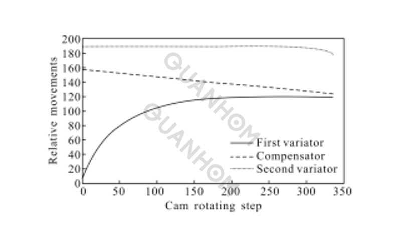
Fig.3 Cam curve of large zoom ratio MWIR optical system
The tolerance requirements are as follows: material refractive index tolerance ± 0.001, Abbe number tolerance ± 0.002; curvature radius tolerance ± 0.02mm; thickness and eccentricity tolerance ± 0.02 mm; tilt tolerance ± 1’.
Components and components are integrated with a lens barrel, and the integration tolerance: eccentric tolerance ± 0.02 mm, tilt tolerance ± 1'; and take the two-stage zoom group as the adjustment compensation. At this time, with a probability of more than 90%, at the cut-off frequency of 331p/mm, the central field of view MTF≥0.22, and the edge field of view MTF≥0.17. The existing processing and assembly level can fully meet the design requirements of the system.
Analysis and summary of the two-element zoom structure in the realization of a large zoom ratio optical system of several problems, on this basis, expounds a two-stage zoom structure of the large zoom ratio continuous zoom optical system realization method, and The distribution of the power of each component and the smoothing of the movement curve of the component in the design process are discussed, which provides a new way for the realization of the large zoom system.
As an example, a compact mid-infrared large zoom ratio continuous zoom optical system was designed. The system uses only two infrared materials, silicon and germanium, to achieve a continuous zoom function with a focal length ranging from 6.5 to 455mm up to 70 times. In addition, the system is small in size, compact in structure, high in transmittance, and has good imaging quality and tolerance characteristics. It is expected to be widely used in early warning, sighting, tracking, monitoring and other fields. The design example also shows that the method can be used for the design of a continuous zoom optical system with a large zoom ratio with similar requirements.
Quanhom has many years of experience in researching infrared continuous zoom lenses, and can provide you with some professional advice to a certain extent.
As a leading manufacturer of Opto-electromechanical components, we have a professional and experienced professional team that continuously develops first-class new infrared technology, and has decades of experience in designing complex infrared optical-related products. Our high-quality thermal infrared lenses (LWIR, MWIR, and SWIR) are well received by users, and our thoughtful one-stop service has also won praise and trust from many customers. If you want to buy our infrared continuous zoom lens, please contact us immediately!
Authors: Qu Rui, Mei Chao, Yang Hongtao, Cao Jianzhong, Zhao Yan
Journal Source: Vol.46 No.11 Infrared and Laser Engineering Nov.2017
Received date: 2017-03-12 date Revision date: 2017-04-17
References:
[1] Ellis I B, James B C, Iain A N, et al. Zoom lens system: US, 6969188 B2[P]. 2005-07-29.
[2] Neil I A. Optimization glitches in zoom lens design [C]//SPIE, 1997, 3129: 158-180.
[3] Sinclair R L. High magnification zoom lenses for 3 -5 mm applications[C]//SPIE, 2004, 3429: 11-18.
[4] Aron Y, Boubis I, Shabit R. T. A novel design of a high magnification athermalized 1:30 zoom in the MWIR [C]//SPIE, 2004, 5406: 97-106.
[5] Hyun Sook Kim, Chang Woo Kim, Seok Min Hong, et al. Compact mid -wavelength infrared zoom camera with 20:1 zoom range and automatic athermalization [J]. Opt Eng, 2002, 41(7): 1661-1667.
[6] Zhou Hao, Liu Ying, Sun Qiang, et al. MWIR continuous zoom optical system with magnification of 45 [J]. Journal of Infrared and Millimeter Waves, 2014, 33(1): 68-77.
[7] Wang Haiyang, Li Li, Jin Ning, et al. Design of MWIR continuous zoom optical systems with large zoom range [J]. Infrared and Laser Engineering, 2013, 42(2): 398-402. (in Chinese)
[8] Zhang Liang. Optical design for middle infrared zoom system [J]. Journal of Applied Optics, 2006, 27 (1): 32 -34. (in Chinese)
[9] Tao Chunkan. Zoom Focus Optical System Design [M]. Beijing: National Defense Industry Press, 1988 (in Chinese)
[10] Lee K H. First order computation for imaging IR optical systems[C]//SPIE , 2003, 5076: 123-129.
[11] Warren J S. Modern Optical Engineering: the Design of Optical Systems[M]. New York: McGraw-Hill, Inc., 2008.
[12] Kingslake R, Johnson R B. Lens Design Fundamentals[M]. Burlington: Academic Press, 2010.
[13] Joseph M G. Introduction to Lens Design with Practical ZEMAX Examples[M]. Richmond: Willmann Bell Inc., 2002.
[14] Wang Zhijiang, Gu Peisen. Practical Optical Technology Handbook [M]. Beijing: Machinery Industry Press, 2006. (in Chinese)
[15] Optical Research Associates. Code V Reference Manual [M]. Pasadena: Optical Research Associates, 2009.