Research and Implementation of Infrared Lens Auto-focus Technology Based on Field Programmable Gate Array
- Share
- Issue Time
- Nov 19,2021
Summary
In view of the general characteristics of vertical fringe noise and random noise in infrared images, this paper improves and optimizes the infrared sharpness evaluation algorithm and the hill-climbing algorithm in the process of focusing.
Autofocus technology plays an important role in the field of infrared thermal imager monitoring. At present, there exist some problems with infrared autofocusing technology, such as low success rate, complex architecture, and low focusing speed. Therefore, this study proposes an autofocusing technology of infrared lens based on FPGA, which realizes the functions of infrared image processing, display, and autofocusing with a single FPGA.
In view of the common characteristics of vertical stripe noise and random noise in infrared images, this study improves and optimizes the infrared definition evaluation algorithm and mountain climbing algorithm in the focusing process. The experimental results show that the algorithm and implementation method proposed in this study can help in focusing on the infrared lens remarkably. Meanwhile, the proposed method has characteristics such as high integration, fast focusing speed, and high success rate, and thus has wide application prospects.
Infrared thermal imaging technology has been widely used in national defense, warfare, detection, monitoring, and other fields in recent years. For thermal imaging monitors used in border and coastal defenses, the infrared turntable needs a fixed period of rotation and positioning during use to achieve the purpose of patrol. Each time it turns to a new position, it needs to be refocused to obtain a clear picture display. Therefore, the automatic focus function of the infrared thermal imager can greatly facilitate the observation and use of the operator.
Compared with visible white light imaging technology, infrared imaging technology realizes imaging of the observed object based on the heating of the observed object itself. Since its imaging principle is inconsistent with the visible white light imaging principle, infrared imaging technology, and white light imaging technology have a certain degree of realization. The difference. Image-based auto-focusing technology has been very mature in white light image processing. In literature [1] and literature [2], the author uses PC and FPGA to complete the lens auto-focus based on visible white light images, respectively.
In practical applications, the performance of the infrared detection imager is affected by many factors such as infrared detectors, analog-to-digital conversion circuits, structural heat dissipation, and optical lenses. The traditional white-light image auto-focusing technology has a poor effect on the auto-focusing of infrared images. Therefore, it is necessary to propose an auto-focus technology based on the characteristics of the infrared image itself (the phenomenon of vertical stripes, excessive noise, etc.).
This paper proposes an FPGA-based infrared lens auto-focusing technology. Compared with the literature [3], it improves the image quality evaluation algorithm for the characteristics of vertical stripes in the infrared image. Compared with the literature [4], the infrared image is noisy. Features Optimize the hill-climbing algorithm to achieve lens control.
Compared with the literature [5], this article does not rely on the participation of the host computer. It is completely implemented by the FPGA itself to achieve image acquisition, image optimization, image definition evaluation, hill-climbing algorithm implementation, motor control, etc. In the work, it greatly improves the integration of the entire thermal imager.
1. The composition of the thermal imager and the principle of automatic focusing
1.1 Thermal imager composition
The thermal imager with the auto-focus function proposed in this paper is shown in Figure 1. The main components include the infrared lens, an infrared detector, image processing circuit, FPGA circuit, DDR3, motor drive circuit, focusing motor, and focusing mechanism (mechanical gear).
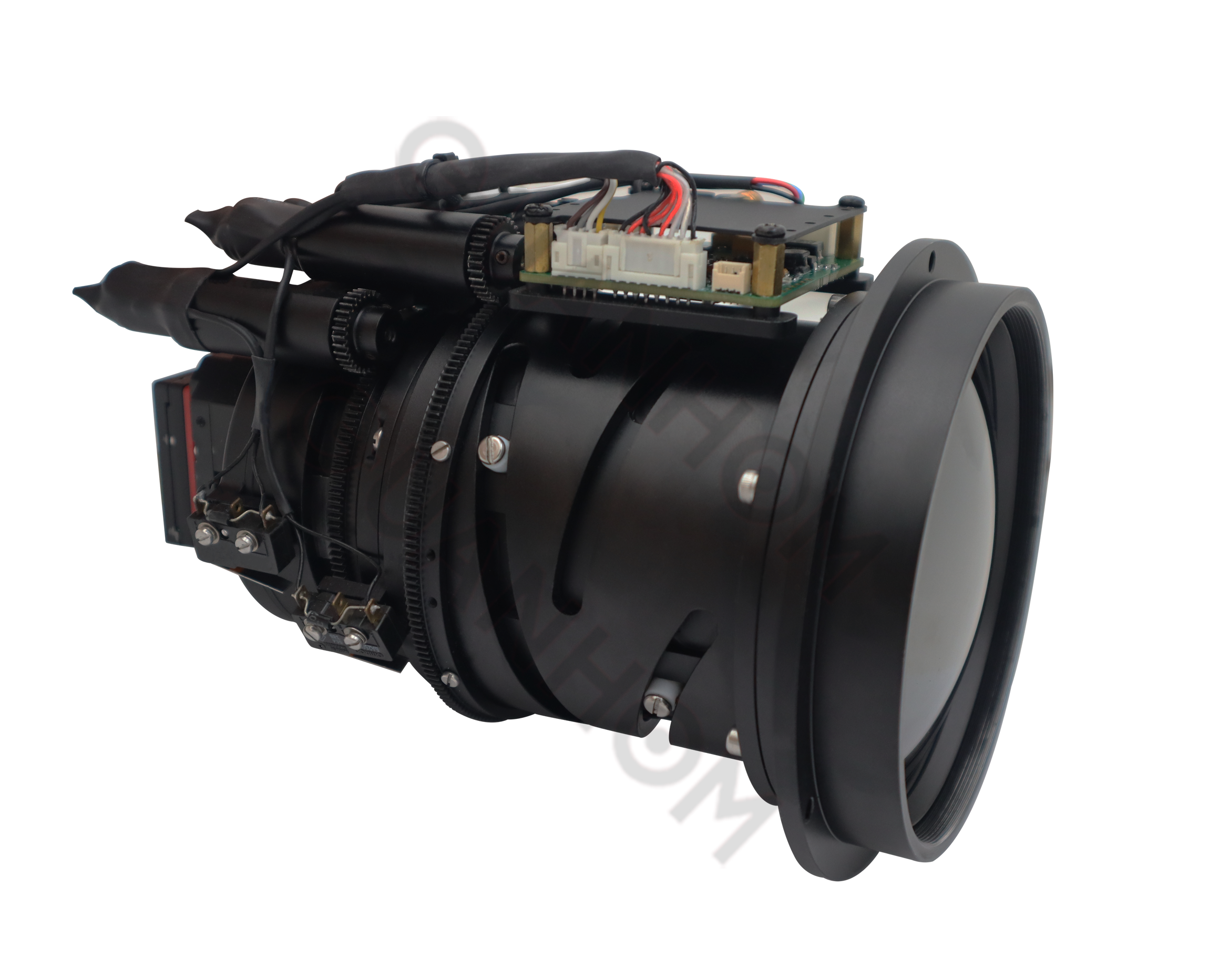
Fig.1 Autofocus infrared thermal imager
1.2 The working principle of the thermal imager and the working principle of automatic focusing
The main architecture of the infrared thermal imager is shown in Figure 2.
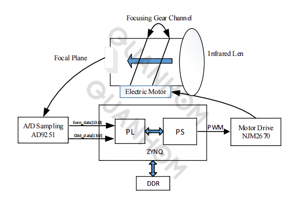
Fig.2 Main structure of infrared thermal imager
From Figure 2 we can see the composition of the entire thermal imager. The workflow of the thermal imager is as follows.
(1) The light enters the focal plane of the infrared detector through the infrared lens. The effective wavelength of the spectrum that the infrared lens can pass is 8-12m, which can filter out visible white light.
(2) The infrared focal plane converts infrared light into electrical signals. The effective imaging resolution of the selected infrared focal plane is 720×576.
(3) The signal output by the infrared focal plane is an analog video signal, which needs to be digital-to-analog converted in the circuit, and the infrared analog signal is converted into even and odd digital video data of 14 bits with the AD conversion chip AD9251.
(4) The parity data needs to be reorganized inside the FPGA, and then post-image processing such as non-uniform correction, image enhancement, vertical striping, and temperature compensation is performed on the infrared image. This part is not the focus of this article and will not be discussed.
In this step, the parity data generated in step (3) needs to be spliced line by line into a complete picture. The gray values of two adjacent pixels in each line of the image come from different sources (parity channels). Produce the "vertical streaks" phenomenon. Vertical stripes are common in infrared imaging. In this step, FPGA optimizes the image to eliminate the interference caused by the vertical stripes and make the entire frame of the image display smoother and smoother.
(5) The processed image data is encoded into a PAL video format through an external circuit and directly output to the display, or it can be compressed and encoded to the server for display through the network. For autofocus, it needs to rely on the image data generated in this step.
(6) Perform image clarity evaluation based on the image generated in (5). FPGA has powerful processing capabilities for parallel data, so a gradient energy algorithm is selected for clarity evaluation. The commonly used gradient energy algorithm requires data processing for all pixels of the entire picture, which requires a relatively large amount of calculation and a long processing time. This paper proposes an improved gradient energy algorithm to evaluate imaging clarity, see Chapter 2 for details.
(7) The PL end of FPGA passes the result of image clarity evaluation to the next link for processing. For this step, the whole (6) and (7) in the design of literature [5] rely on the PC implementation of the host computer. This article will continue to implement automatic focusing based on clarity within the FPGA.
(8) The PL end of FPGA uses the hill-climbing algorithm to control the motor according to the definition evaluation data and then adjusts the lens focal length, finally obtaining a clear picture and completing focusing.
The hill-climbing algorithm is widely used in the automatic focusing of visible light imaging. However, due to the large noise and vertical stripes of the infrared image itself, a "pseudo hilltop" state will appear during the climbing process. The existence of "false hilltops" will directly lead to the failure of autofocus. For this reason, this article has optimized and improved the hill-climbing algorithm, see Chapter 3 for details.
In summary, the realization process of automatic focusing is shown in Figure 3. The whole process is a closed-loop feedback process, which requires repeated adjustment and optimization to finally achieve the clearest state of the image, that is, the focused state. This article uses Xilinx's ZYNQ series FPGA FXC7Z030-2FBG676 to implement the above steps (4) to (8). ZYNQ is divided into PL end and PS end.
The PL end is a programmable logic gate array for image processing and definition evaluation, and the PS end is an ARM core, which is used to implement hill-climbing algorithms and motor control. At the same time, the FPGA is externally equipped with two DDR3 chips, the model is Micron's MT41J128M16HA, with a single chip capacity of 256 MB and two chips with a capacity of 512 MB, which are used to cache video image data.
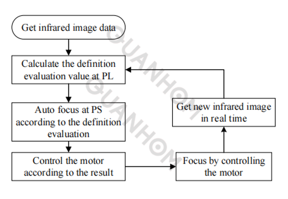
Fig.3 Autofocus process
2. Realization of infrared image quality evaluation in FPGA
2.1 Clarity evaluation algorithm
Literature [6] gives a comprehensive and specific introduction to the definition evaluation algorithm, combining the characteristics of infrared images and the difficulty of FPGA implementation. In this paper, a gradient energy algorithm is used to judge the sharpness of the image.
As shown in Figure 4, the sum of square differences is performed on the gray values of the pixels in the 3×3 mask area of the picture pixels.
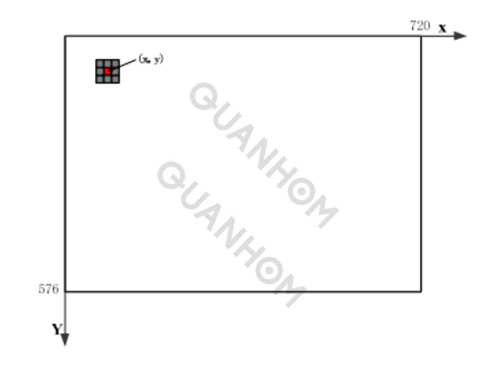
Fig.4 Calculation of gradient energy using 3×3 mask
For the pixel (x, y) in the figure, define its energy value as F(x, y) as the sum of the squares of the gray values of its surrounding 8 neighboring pixels and their differences. As shown in formula (1):
Add the sum of all the pixel gray difference squares to get the gradient energy value of an image:

For a high-definition picture, because the image details are more, the gradient energy value Fvalue will be a relatively large value. For a blurred picture, the value of each pixel is not much different, and the value of Fvalue is also very small. For a single-pixel picture (all pixel values are the same), Fvalue=0.
Therefore, the value of Fvalue can reflect the degree of image detail, which in turn reflects the clarity of an image. Gradient energy algorithm can evaluate the sharpness of the image. This article uses this algorithm to evaluate the sharpness of the infrared image.
2.2 Improvement of Gradient Energy Algorithm in the Judgment of Infrared Image Definition
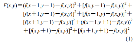
The gradient energy mentioned in section 2.1 has a good result for evaluating the clarity of visible white light images. However, because the infrared images are spliced by odd and even column data (step 3 mentioned in section 1.2), the left and right adjacent pixels are grayed out. The degree value is very different, and the focusing effect of directly using the traditional gradient energy evaluation algorithm is not good. This article has made certain improvements to the algorithm in response to this phenomenon, using a 3×5 mask instead of a 3×3 mask, which can avoid the difference caused by the picture pixels of different video sources and reduce the noise caused by vertical stripes to the smallest.
At the same time, in view of the time requirements of the thermal imager's automatic focusing, the gradient energy calculation used in this article does not calculate the pixel value of the entire picture but takes the pixels in the middle 1/3 area for calculation, so that the calculation amount is calculated for the entire picture 1/9 of the amount. After a lot of experimental verification, the autofocus effect calculated by taking the 1/3 area of the center of the picture is consistent with the effect of the whole picture.
The improved mask and center area selection are shown in Fig. 5.
2.3 Implementation of the improved algorithm in FPGA
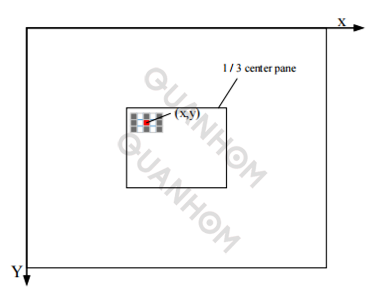
The PL end of FPGA uses FIFO and register to realize the buffer of 9 data of mask window. The program on the PL side needs to complete ①design the timing of the FIFO read and write control signals; ②cache the data of the 3×5 mask; ③calculate the sum of the variance of a single-pixel 3×5 mask, and output the data.
Figure 6 shows the schematic diagram of the FPGA internal read and write control of FIFO. When the first row of data arrives, write it into FIFO1; when the second row of data arrives, read the first row of data stored in FIFO1 and write it into FIFO2, and write the second row of data to FIFO2 at the same time medium; when the third row of data arrives, read the data in FIFO1 and FIFO2 at the same time. At this time, the third row of data enters the subsequent register group REG1 together with the first and second rows of data stored in FIFO1 and FIFO2 ~REG9. The data of REG1~REG9 respectively represent (x-2,y-1), (x,y-1), (x+2,y-1), (x-2,y), (x, y), (x+2,y), (x-2,y+1), (x,y+1), (x+2,y+1) 9 points.
Fig.6 Cache 3×3 mask data by FIFO and register
According to the 9 data in the REG1~REG9 registers in Figure 6, FPGA calculates the variance of the gray values of the pixels in REG5 and the remaining 8 registers (formula (1)). Since the improved algorithm only calculates the middle 1/3 area, the program sets the column counter and the row counters to count the rows and columns of a frame of the picture. When the column counter counts to 241~480 and the row counter count to the range of 193~384 ( This range means that for a 720×576 resolution screen, 1/3 of the pixel point in the center area), the pixel data is considered to be available for calculation. Accumulate the variance values of all pixels in this range, and finally obtain a 32-bit gradient energy value (formula (2)).
According to the theory introduced above, the larger the 32bit value, the clearer the image, which provides a basis for mountain climbing to achieve focus adjustment later.
3. Implementation of the improved hill-climbing algorithm in FPGA
3.1 Automatic focusing based on a hill-climbing algorithm
Reference [7] has a more detailed introduction to the hill-climbing algorithm. As shown in Figure 7, the basic principle of the hill-climbing algorithm is a process of continuously approximating the maximum gradient energy value. As can be seen from the auto-focusing flowchart in Figure 3, the image will change after each focusing, and the gradient energy will also change accordingly. In this continuous change process, find the maximum gradient energy value, which is the clearest moment of the image. The lens position corresponding to the clearest picture is the focus position.
It can be seen from the schematic diagram in Figure 7 that there are 8 mountain climbing steps in the focusing process. The first 3 steps are always in the "uphill" process, and the 4th and 5th steps are in the "downhill" process. At this time, the picture has become worse than the previous step 3, so the 6th and 7th steps start to "back up the mountain". After the 7th step, I have already passed the top of the mountain, so I changed the step length and finally climbed to the "top of the mountain" at the 8th step to complete the focusing work.
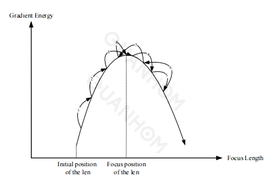
Fig.7 Hill climbing algorithm
In actual work, the climbing process can often be completed within 8 attempts, during which it is necessary to continuously adjust the step length to achieve the purpose of focusing.
3.2 Improvement and realization of the hill-climbing algorithm in infrared lens automatic focusing
Figure 7 shows the implementation of mountain climbing under the white light screen, which is relatively ideal. For infrared images with relatively large noise, there will be multiple “mountain tops” during the climbing process, as shown in Figure 8.
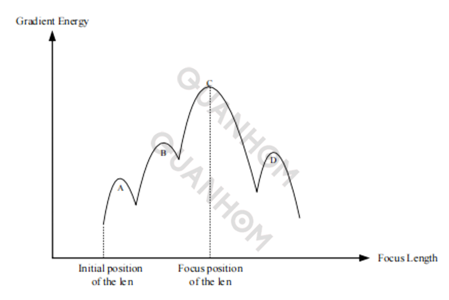
Fig.8 Hill climbing of infrared image focusing
A, B, and D in Figure 8 are "pseudo mountain tops", which are caused by noise in the infrared image. According to the standard process of mountain climbing, starting from the initial position of the lens to climb the mountain, it is easy to misjudge A as the top of the mountain. At this time, the purpose of focusing cannot be achieved. For this reason, this paper optimizes the mountain climbing algorithm for infrared image auto-focusing as follows.
(1) The PS end of the FPGA receives the gradient energy value transmitted by the PL end to determine whether to climb the mountain. In order to reduce the influence of noise, every 3 values received are averaged as a basis for mountain climbing, that is, to calculate the average value of three gradient energy values for a fixed picture, so as to reduce the influence of random noise on the picture clarity evaluation.
(2) Regarding the judging mechanism of whether to "turn back and climb the mountain", it is judged that at the current step length, if it is "down the mountain" twice in a row, then it starts to look back. Under this mechanism, the relatively small peaks of A and B will rebound in the gradient energy value during the second determination process, which is judged to be a false peak, but this situation will not occur at the true peak C.
Based on the above two optimization schemes, the process of auto-focusing on the FPGA-based PS side of this article is shown in Figure 9.
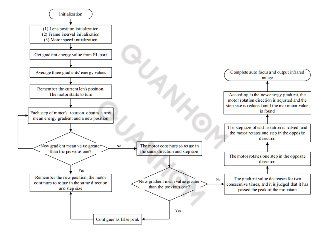
Fig.9 The improved hill-climbing algorithm implemented on FPGA PS
4 Function realization and performance test
4.1 Focusing effect
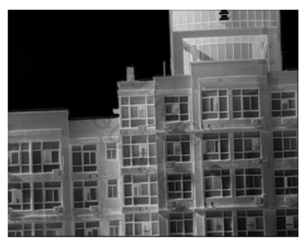
The auto-focusing technology proposed in this paper and the auto-focusing methods proposed in the literature [2] and literature [4] are reproduced and compared respectively. As shown in Figure 10.
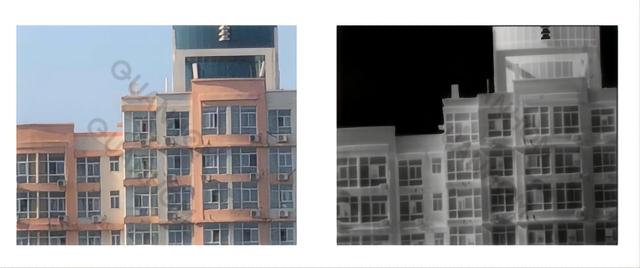
(a)Visible light image (b) Infrared original image
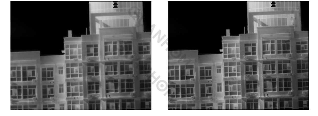
(c) Image implemented in document[2] (d) Image implemented in document[4]
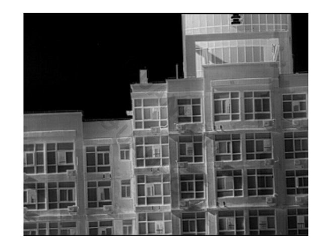
(e) Image implemented with the method proposed in this paper
Fig.10 The effect of autofocus proposed in this paper is compared with other schemes
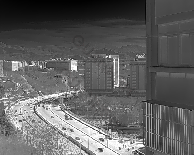
The 4 infrared pictures in Figure 10 show the focusing effect of the infrared lens. For this focusing process, since the original picture is relatively clear, it will test the focusing algorithm's ability to read and process the details of the picture. To objectively evaluate the sharpness of the four pictures (b), (c), (d), and (e), the "gray-scale variance value" proposed in Reference [8] is used to evaluate the sharpness of the four pictures.
Compared with a blurry image, a sharply focused image should have a larger grayscale difference between its data, that is, its variance should be greater. The sharpness of the image can be measured by the variance of the image grayscale data, the greater the variance, Which means the better the clarity.
Calculate the gray-scale variance value of the picture in MATLAB, and the results are shown in Table 1.
Table 1 Gray variance of four pictures
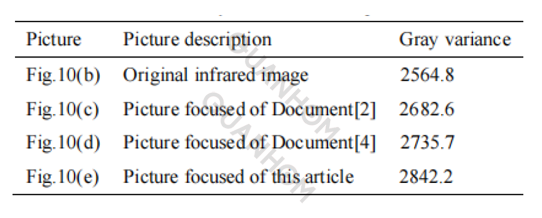
It can be seen from the picture in Figure 10 and Table 1:
The original infrared image (b) has not undergone any focusing processing. Although the image can show the image of the object, it is still a bit blurred by the naked eye, and its gray-scale variance value is relatively small, indicating that the details are not enough.
(c) The picture is processed by the white light image focusing method, without considering the vertical stripe noise characteristics of the infrared image, so the focusing effect is general, and it can be seen from the gray-scale variance value.
(d) The display effect of the picture is improved to a certain extent compared with (c), but it cannot reach the effect of the algorithm (e) proposed in this paper. It should be that the optimization algorithm in the climbing process is not good enough.
(e) The picture shows the focused display effect achieved by the algorithm proposed in this paper. It can be clearly seen that the display effect is better than (d) and (c).
The defining quality of the picture can also be seen from the magnitude of the gray-scale variance value of the four pictures in Table 1, and the picture after the focus of the algorithm proposed in this paper is the clearest. It shows that the algorithm proposed in this paper has a good performance and effect in the auto-focusing process.
Figure 11 compares the focus display image obtained after calculating the gradient energy value of the whole picture and calculating the gradient energy value of the 1/3 area. The picture (b) in Fig. 11 is the picture (e) in Fig. 10.
(a) Whole image gradient energy calculation
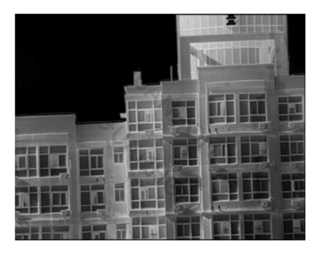
(b)1/3 image gradient energy calculation
Fig.11 Comparison of image display based on gradient energy of two regions
From the comparison of the two images in Figure 11, there is basically no difference. The difference of the gray-level mean square value of the two is less than 1, which shows that the method proposed in this paper to obtain the gradient energy value from the center 1/3 of the image is feasible. The advantage of this optimized and improved algorithm is that it saves autofocus time and FPGA resource consumption to a large extent.
4.2 Hill climbing curve during focusing
This section analyzes the hill-climbing curves of the three algorithms in the process of auto-focusing. Since the entire mountain climbing is realized based on the rotation of the motor, the entire mountain climbing process can be observed through the angle of the motor rotation.
The following compares the three algorithms (reference [2], reference [4], and this article) in the autofocus process, the motor rotation, and the final focus. After the previous test, it is concluded that the motor needs to rotate 751 in the positive direction from the initial position to the focus position, which is the horizontal reference dotted line in Figure 12.
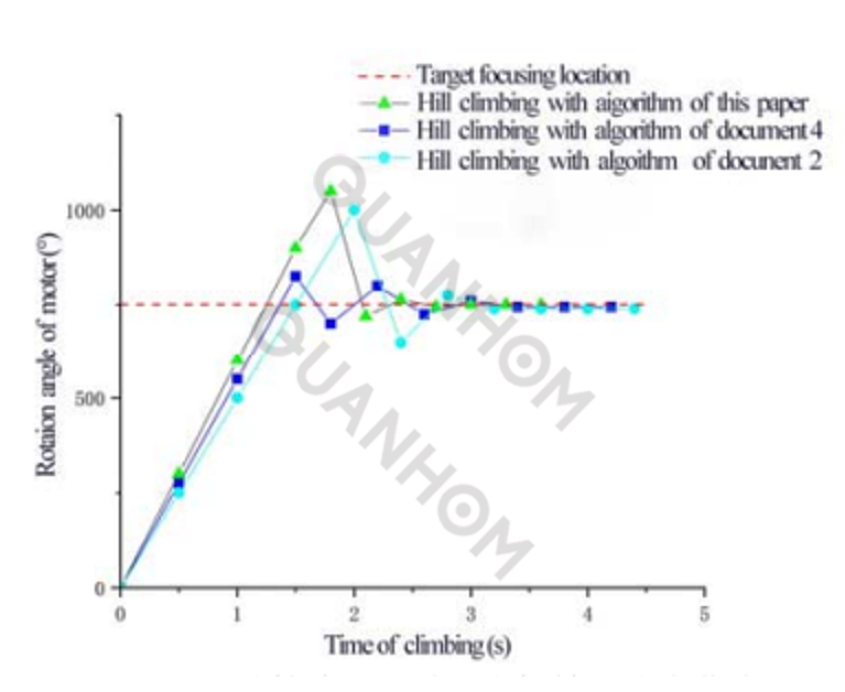
Fig.12 Focusing curves of motor rotation with three algorithms for mountain climbing
It can be seen from Figure 12:
(1) The mountain climbing algorithm proposed in this paper has a relatively large step in the early stage, so it can climb to the top of the mountain quickly. At the end of the third climb, it has exceeded the top of the mountain, so the step length of the fourth climb is reduced to judge whether it is a "pseudo mountain top";
(2) The three algorithms are more accurate in judging the "mountain top" because the image itself is relatively clean and the noise is small, so the secondary climbing proposed by the algorithm in this paper does not play a role here;
(3) The algorithm proposed in this paper and the algorithm proposed in the literature [4] are more responsive than the algorithm proposed in the literature [2] in judging the downhill trend, and the control is better;
(4) The algorithm proposed in this paper basically reached a stable state (end of focus) after the seventh climb and reached the end of focus at the thirds, and the other two reached a stable state after the eighth climb. The literature [2] The algorithm in [4] takes 3.6 s, and the algorithm in [4] takes 3.4 s;
(5) The three algorithms have differences in the setting step size and each operation time, so it can be seen from Figure 12 that the time of the climbing process in the early stage is relatively consistent, and the time is inconsistent if there is no adjustment in the later stage;
(6) From the perspective of the final focusing effect, the algorithm proposed in this paper is better than the focusing effect of literature [2] and literature [4], and the focusing effect of literature [2] is the worst, which is the same as the focusing effect shown in Figure 10.
4.3 Autofocus time test
The infrared lens auto-focusing system based on FPGA architecture can complete auto-focusing work better. The single-CPU work mode also has a great advantage over other architectures in terms of product integration.
At the same time, this system also has a better performance in real-time. Judging from the references, other schemes do not elaborate on the auto-focusing time too much. For the design proposed in this article, it can be controlled within 5 s from the start of imaging to the completion of focusing. The main time consumption analysis is shown in Figure 13. The total time is 3.55 s, which is better than the autofocus time of most infrared cameras on the market.
4.4 FPGA resource consumption
This paper uses 1/3 of the entire screen to calculate the gradient energy value, mainly to save FPGA resources and calculation time. From the calculation time, the difference between the calculation of the pixel gradient energy of the whole picture and the calculation of 1/3 area is 42.84-4.76 = 38.08 ms. Although this time is small for the 4.55 s used in the entire focusing process, it is a relatively long time for the operation of the FPGA internal program.
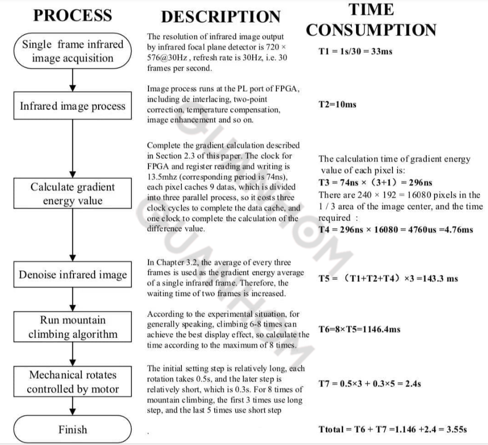
Fig.13 Time spent on autofocus
For FPGA internal resource consumption, the difference between the two is also relatively large. Table 2 lists the consumption of FPGA resources by the two methods.

It can be seen from Table 2 that the auto-focus method used in this article does not use many internal FPGA resources, even if it is done for the entire screen, the resources of XC7Z030 are sufficient. But for FPGAs, the fewer resources are used, the more controllable the program is.
Aiming at the lens auto-focusing of the infrared thermal imaging device, this paper proposes an FPGA-based infrared lens auto-focusing technology. Compared with the visible white light auto-focusing technology and the traditional infrared focusing technology, the technology proposed in this paper has three major improvements:
①The whole machine uses a single FPGA processor to complete the infrared image processing and display and lens focusing work, which greatly improves the integration of the product;
② Aiming at the characteristics of infrared images and the advantages of FPGA parallel processing of data, an improved gradient energy algorithm is proposed, which can truly evaluate the clarity of infrared images;
③According to the characteristics of infrared images, the mountain climbing algorithm is improved and optimized to effectively filter out false mountain tops and achieve the purpose of mountain climbing.
This paper verifies the above three technical improvements, and the results also verify the superiority of the algorithm proposed in this paper. At present, the auto-focus technology proposed in this article has been maturely applied to thermal imager products, and its functions and performance are at the industry-leading level, and it has a good promotion significance. As an expert in infrared thermal imaging cameras for many years, Quanhom can share some professional and comprehensive knowledge in infrared optics.
As an experienced manufacturer of Opto-electromechanical components, Quanhom is committed to providing users with a variety of thermal infrared cameras (LWIR, MWIR, and SWIR) of excellent quality. We have a good reputation in the industry by virtue of leading R&D technology and excellent manufacturing technology. And our products are sold all over the world and have received praise and trust from many customers. If you want to learn more about our related services, you can send us your needs, and we will give you a satisfactory answer as soon as possible.
Authors: Sun Shaowei, Yang Yuetao, Yang Bingwei, Wan Anjun, Zhong Hailin
Journal Source: Vol.43 No.5 Infrared Technology May 2021
Received date: 2020-11-07; revised date: 2021-03-24.
References:
[1] ZHAO Zhibin. Research on Automatic Focusing Technology of Visible Light Camera for Airborne Photoelectric Platform[D]. Graduate School of Chinese Academy of Sciences (Changchun Institute of Optics, Precision Machinery, and Physics), 2010.
[2] NI Wenjia. Auto-Focusing Video Monitoring System Based on FPGA[D]. Wuhan: Wuhan University of Technology, 2012.
[3] LI Shenyang. Auto-Focusing Algorithm Based on Infrared Image Energy Value[J]. Shanxi Electronic Technology, 2014(4): 6-9.
[4] ZHANG Bo, ZHANG Gang, CHENG Yongqiang. Design of Video Processor WithAuto Focus Function[J]. LCD and Display, 2010, 25(3): 396-400.
[5] WAN Xiaofan, LYU Yaowen, ZHANG Dongyan. Design of an Auto-focusing Infrared Thermal Imager Online System[J]. Infrared Technology, 2018, 40(8): 743-748.
[6] WANG Jian. Research on Automatic Focusing Technology Based on Image Processing[D]. Chengdu: Graduate School of Chinese Academy of Sciences(Institute of Optoelectronic Technology), 2013.
[7] XU Zhili. Research on SEM autofocusing system based on FPGA[D]. Nanjing: Southeast University, 2016.
[8] CHEN Guojin, ZHU Miaofen, ZHANG Kesong. Study on a sharpness evaluation function of image focusing processk[J]. Data Acquisition and Processing, 2009, 24(2): 165-169.