Optimal Design of Cam for Zoom Lens
- Share
- Issue Time
- Nov 12,2021
Summary
The optimization of the zoom cam is the key to the realization of the optical design goal and finally the realization of the zoom lens. This article will specifically discuss the cam optimization design of the zoom lens.
The rapid development of optical design and manufacturing technology, precision machinery manufacturing technology, CCD manufacturing technology, and electronic technology, combined with the variability of the field of view (focal length) of the zoom lens, makes the zoom lens more and more widely used.
At present, the zoom lens generally adopts a mechanical compensation optical structure, and the number of variable components is mostly two groups or more. The optical design of the zoom lens and the structural design of the zoom movement mechanism are both difficult.
The optimization of the zoom cam is the key to the realization of the optical design goal and finally the realization of the zoom lens. The design of the military zoom lens must also consider the smoothness of the zoom movement and the speed of the zoom process. This article mainly discusses the optimization method of the two-variable element mechanical compensation type zoom lens cam.
Main technical requirements
According to actual application requirements, the main design indicators of the zoom lens are as follows:
(1) Mass: m≤1500g;
(2) The focal length is 24~120ram, the whole zooming time is 6s±1s;
(3) The maximum equivalent relative aperture is 1:4.0;
(4) Optical transfer function:
0 Field of view: MTF≥0.6(21lp/mm)
0.71 field of view: MTF≥0.5 (15lp/mm);
(5) The image plane displacement during zooming is not more than ±0.1mm;
(6) The displacement of the optical axis during zooming is not greater than ±0.12mm.
Optimization of zoom cam
Figure 1 shows the optical structure of a zoom lens. The lens adopts a two-variable component mechanical compensation scheme with negative group variable magnification and positive group compensation.
The single-double structure zoom group and the single-single structure compensation group have a one-to-one correspondence between the moving positions and must be controlled by a complex cam mechanism. Theoretically, the image planes of all focal lengths can be kept consistent.
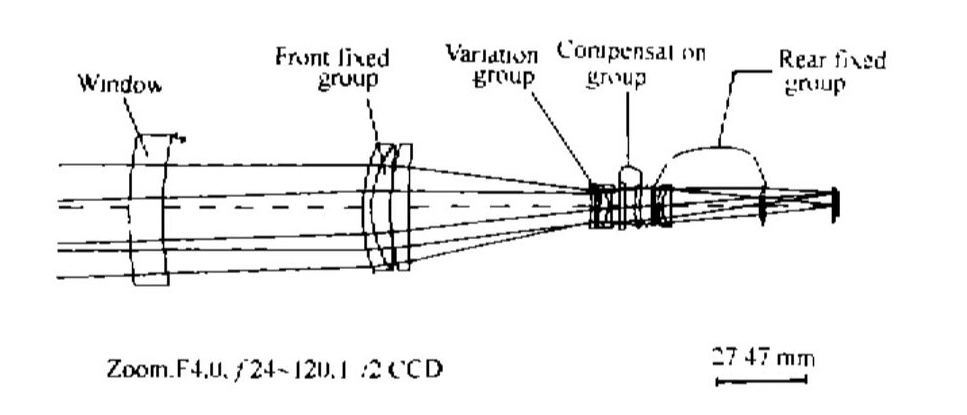
Figure 1: Optical form of a zoom lens
After the optical parameters of the zoom lens are optimized and determined by the optical design, a series of cam data points corresponding to each other must be calculated. The calculation of cam data is the prerequisite for the precise machining of mechanical cams. The amount of data needs to be determined by trial.
In order to ensure the accuracy of the cam and the smoothness and rapidity of the zoom movement, the step length of the cam line is required to be between 002 and 0.05 mm. At the same time, The rise angle of the two sets of cam curves should be as small as possible and balanced.
There are many ways of cam calculation, but Macro-PIUS macro language programming is required in CODE V optical design software. The part of the macro program compiled during the cam optimization process is given below. Using this program, the CODE V optical design software can be used to realize the cam optimization of a two-variable-element continuous zoom lens.
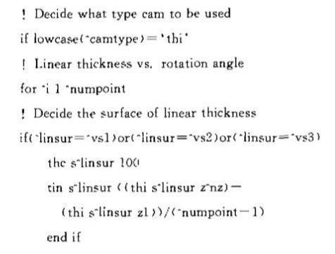
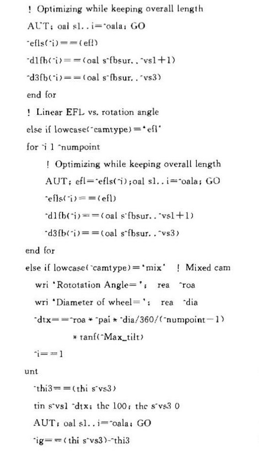
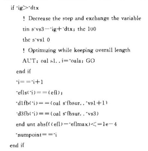
Using the main body of the program, the three types of cams are optimized and compared for the developed continuous zoom lens.
(1) The cam angle has a linear relationship with the focal length
Figure 2 is a schematic diagram of the result of optimizing the cam curve into a linear relationship between the cam rotation angle and the focal length change. The designed cam has a small lift angle at the medium and long focal lengths, but the local lift angle in the range of 15mm at the short focal length end is large, up to 67°, the cam is difficult to drive and the driving torque is unbalanced, so this optimization method is not feasible.
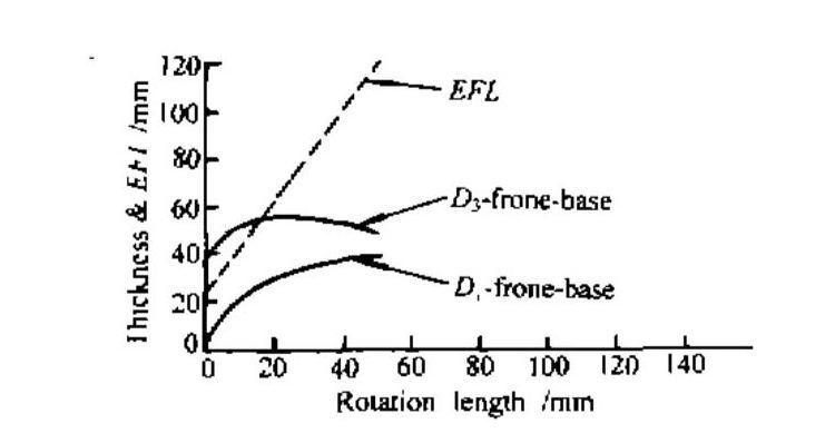
Figure 2: Cam rotation angle is linear with EFL
(2) The cam angle has a linear relationship with the variable interval
Fig. 3 is a schematic diagram of the result of optimizing the cam curve into a linear relationship between the cam rotation angle and the variable air interval. The designed cam has acceptable lift angles in the medium and short focal lengths, but the local lift angle in the 20mm range of the long focal length is larger, up to 56°, which is not conducive to cam drive and dynamic torque balance. This method is not advisable.
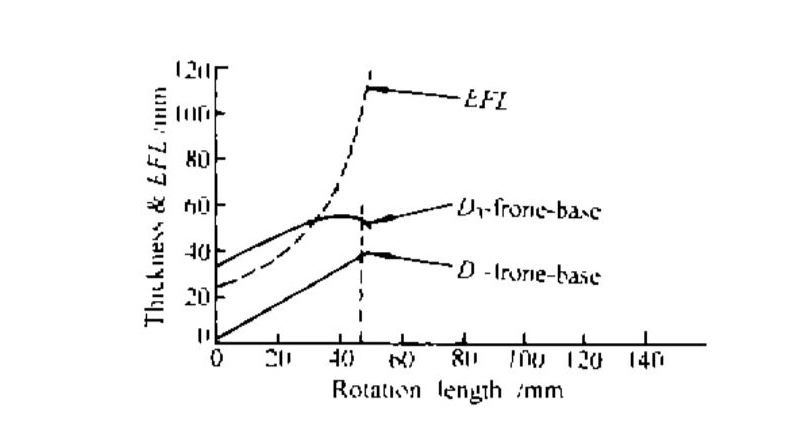
Figure 3: Cam rotation angle is linear with variable thickness
(3) Hybrid optimized zoom cam
Combining the advantages of the two linear cam optimization methods shown in Figure 2 and Figure 3 in the design, the cam is used for hybrid processing, the short focal length and the middle focal length are used for variable interval linear change processing, and the long focal length is used for focal length linear change processing.
After trying, a hybrid cam as shown in Figure 4 was obtained. The full lift angle of the passive cam is less than 38°, and the local maximum lift angle of the action cam is 39°. The lift angles of the two cams match well, the cam movement is smooth throughout and the driving torque is balanced, so this optimization method is adopted.
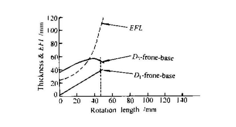
Figure 4: Mix-optimized cam
In the optimization process of the above three types of cams, the two cam curves are based on a specific common surface, and their drawing is automatically realized by running the self-made Macro-PLUS macro program through the UGR option function of CODEV.
The rotation length is determined by the expected diameter and the expected rotation angle of the cam. Since the axial length of the zoom group and the compensation group of the system are very short, the mechanical structure of the zoom group and the compensation group has a relatively large diameter.
In order to ensure the smoothness of the zoom movement, the cam adopts the "diameter double drive" method to drive the movement of the zoom group and the compensation group. Therefore, after considering the strength of the cam mechanical components, a predicted cam rotation angle of 160° is adopted.
The result of the hybrid optimized cam in Fig. 4 has been practically applied in the two sets of zoom lenses that have been developed. Tests such as optical inspection, vibration, high and low temperature, and actual use show that the optical design and cam optimization of the zoom lens is successful.
The test run of the Macro-PLUS macro program compiled by myself for different cam data points and different two-component optical designs shows that the procedure and control method of the program are completely suitable for the cam optimization design of other two-component mechanically compensated zoom lenses.
Quanhom Continuous optical zoom LWIR lens with balance of aperture lightweight and costs, ideal for long-range surveillance and security, support SXGA(1280x1024 12μm) format. As an expert who has studied infrared zoom lenses for many years, Quanhom can give you professional advice to a certain extent.
Quanhom is a manufacturer of Opto-electromechanical components with many years of experience. With our excellent R&D technology and rigorous manufacturing attitude, we have become a leader in this industry. We are equipped with a professional quality inspection system and a comprehensive management team to control all aspects from product manufacturing to export. At the same time, we will also provide users with thoughtful one-stop service and effective solutions. If you are interested in our infrared zoom lens, please contact us immediately!
Authors: Junhe Meng, Zhen Zhang, Xingwen Sun (Tianjin Institute of Technical Physics, Tianjin 300192)
Journal source: Vol. 31 No.1, Infrared and Laser Engineering, Feb.2002
Received Date: 2001-05-23 Revised Date: 2001-10-12
About the author: Junhe Meng (1963-), male, native of Tianjin, researcher, master's tutor, mainly engaged in optical design research, and published more than 10 papers.
References:
[1] Optical Research Associates CODE V Reference manual[M]. California:O R A.1999.9-29~9-34.
[2] 王之江,光学技术手册(上册)[M],北京:机械工业出版社,l987.1119-1166.
[3] 袁旭沧, 光学设计[M],北京:北京理工大学出版社.1988.276-280.
[4] 张以谟,应用光学(下册)[M],北京:机械工业出版社.1982.148-168.
[5] 李士贤,李林,光学设计手册[M],北京理工大学版杜,1996.
[6] 电影镜头设计组,电影摄影物镜光学设计[M],北京中国工业出版社.1971.167-259.
[7] 常群, 光学设计文集[M], 北京:科学出版社,1976.16-76.
[8] 陶纯堪,变焦距光学系统设计[M],北京:国防工业出版社,1989.
[9] 帕霍莫夫;白淑惠 变焦距系统[M],北京:国防工业出版社,1980.
[10] 林大键,工程光学系统设计[M],北京:机械工业出版社,1987.
[11] 王子余,几何光学和光学设计[M],浙江:浙江大学出版社,1989.