Design Example of Super Field of View Infrared Optical Lenses
- Share
- Issue Time
- Oct 28,2021
Summary
By understanding the design examples of the super field of view infrared optical lens, we can judge its performance and characteristics more intuitively. This article will specifically share the requirements and analysis of the design example.
In the above, we mainly talked about the design characteristics of the super field of view infrared optical lens. This article will combine these design features to give specific design examples so that everyone can more intuitively feel and analyze the performance of the super field of view infrared optical lens.
A specific design example is given below, and the specific requirements are as follows:
1. Requirements for the field of view layout
(1) Field of view splicing range: 4π spherical airspace
(2) Number of optical lenses: 6
(3) The field of view of a single optical lens is consistent
(4) The overlapping rate of the adjacent lens field of view is not less than 4°
2. Detector
(1) Number of pixels: 1 024 × 1 024
(2) Pixel size: 15 μm
(3) F/#: 2
3. Optical design requirements
(1) Wavelength: 3.7~4.95 μm
(2) Illumination of edge field of view≥90%
(3) IFOV non-uniformity≤±5%
(4) MTF: ≥0.4(@33lp/mm)
(5) Energy convergence: ≥60% (15 μm)
(6) Atermalized temperature range: −55~70℃
(7) Lens length: ≤70 mm
According to the requirements of the field of view, the minimum design field of view of the optical system can be obtained by numerical iterative calculation as 116°. At this time, the effective imaging field of view of each optical lens on the image plane of the detector is shown in Figure 5, and the calculated field of view overlaps The minimum rate is 4°, the maximum is 12.7°, and the pixel utilization rate of the detector is 96.5%.
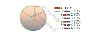
Fig.5 View layout plan of optical lens actual imaging field
The infrared detector is a cooling type. In order to achieve 100% cold aperture efficiency and a large field of view, the optical system should adopt the optical configuration shown in Figure 3; to ensure that the angular resolution non-uniformity of each pixel in the full field of view is ≤±5%, Adopts h = f θ projection method; uses diaphragm coma to introduce a large number of negative vignetting outside the axis to improve the illuminance at the edge of the field of view; in order to meet the excellent image quality of the optical system in the range of −55~70 ℃, adopt optical passive Atermalized design scheme.
The final optimized optical path diagram is shown in Figure 6. The system uses only four lenses to achieve an Atermalized design without diffractive surfaces; compact structure, with a total lens length of 69 mm; among them, the optical and mechanical structural parts are machinable and lightweight. In consideration of environmental adaptability, aluminum alloy 7075 is selected, with a thermal expansion coefficient of 23.6×10⁻⁶ /℃.
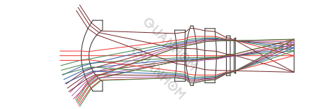
Fig.6 Optical system diagram
By introducing a large number of negative vignetting to improve the illuminance of the edge field of view, the final optimization result is shown in Figure 7. The illuminance of the edge field of view is 90.3% of the central field of view, which meets the design requirements.
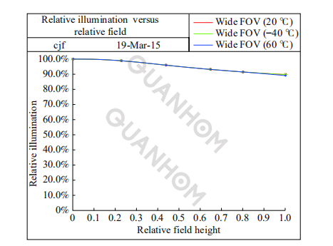
Fig.7 Illumination diagram of each field of view
The energy convergence degree of a single-pixel (15 μm) of the optical system at 20, −55, 70 ℃ is shown in Figure 8. It can be seen from the figure that the energy concentration of a single-pixel in the entire field of view is uniform within the range of −55 to 70 ℃. More than 75%.
The analysis of optical system distortion and angular resolution is shown in Figure 9. The red curve is the f − θ distortion curve, and the green curve is the angular resolution curve. It can be seen from the figure that the maximum deviation of the angular resolution of each pixel in the full field of view (±58°) is 2.5%.
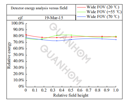
Fig.8 Detector energy diagram of each field of view
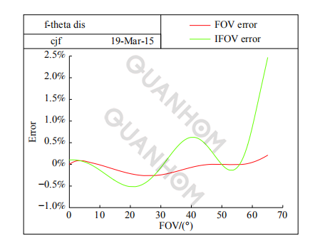
Fig.9 Distortion and angular resolution of each field of view
In the optical design software CODEV, the default tolerance setting is used for analysis, and the result is shown in Figure 10. It can be seen from the figure that the tolerances of each field of view are in good agreement. At the 33 cycles/mm space alignment, there is a 97.7% probability that the MTF of the full field of view in the sagittal direction is better than 0.42, and the MTF of the full field of view in the meridian direction is better than 0.4.
Based on experience, meet the requirements of use. In the stray light simulation software Tracepro, the cold reflection opposite optical path simulation model is established, as shown in Figure 11 (a), and Figure 11 (b) shows the illuminance distribution received by the image surface opposite optical path simulation; Figure 11 (c) gives The equivalent temperature difference distribution in the working band of the image surface is shown. Usually, the system NETD is around 25 mK.
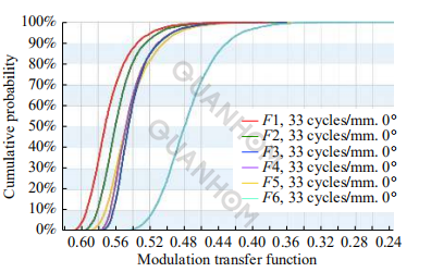
(a) Sagittal direction
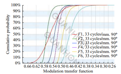
(b) Tangential direction
Fig.10 Tolerance analysis
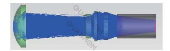
(a) Narcissus analysis modeling
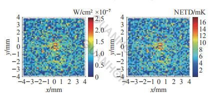
(b)Illumination distribution (c) NETD distribution
Fig.11 Modeling and simulation results of narcissus analysis
It can be seen from the figure that the maximum equivalent temperature difference of cold reflection is 17.3 mK, which is less than the system NETD, and cold reflection meets the requirements of use.
The super field of view infrared optical lens, whose field of view is generally above 90°, is mainly used in the military to warn and indicate incoming missiles or infrared threat targets. It is an important military optoelectronic product. Compared with conventional infrared optics, the super field of view infrared optical lens has many different characteristics. The specific design examples are given in the article, which has a certain guiding significance for the design of this type of optical system.
If you want to learn more about this after reading the above. As an experienced infrared optical lens expert, Quanhom can provide you with a variety of professional advice.
Quanhom is a professional manufacturer of Opto-electromechanical components, we are committed to producing various infrared thermal imaging lenses (including LWIR, MWIR, and SWIR). We have an experienced production team and a strict quality inspection system to conduct strict tests and inspections on the quality of our products, which has won unanimous praise from many customers. We always put the needs of customers in the first place and can provide customers with effective solution technology and thoughtful one-stop service, If you are interested in our infrared optical lens, please contact us immediately!
References:
[1] Zhang Yuansheng. Development of airborne electro-optical warning system [J]. Electronics Optics & Control, 2015, 22(6): 52−55. (in Chinese)
[2] Huang Fuyu, Shen Xueju, He Yongqiang, et al. Performance analysis of the super-wide field of view imaging system used for space target detection [J]. Infrared and Laser Engineering, 2015, 44(10): 3134−3140. (in Chinese)
[3] Yang Shengjie. Optical design for high resolution cooled mid wavelength infrared wide-angle imaging system [J]. Acta Optica Sinica, 2012, 32(8): 0822003. (in Chinese)
[4] Hirsh I, Shkedy L, Chen D, et al. Hybrid dual-color MWIR detector for airborne missile warning systems[C]// Proceedings of SPIE,2012, 12: 83530H1-12.
[5] Tao Zhi, Wang Min, Xiao Weijun, et al. Design for cooled dual-band infrared refractive-diffractive hybrid optical system of athermalization and wide FOV [J]. Acta Photonica Sinica, 2017, 46(11): 1122004. (in Chinese)
[6] Oskotsky. Wide angle MWIR F-Theta lens:Russia, 236344A1[P].2018.
[7] Chen Chen, Hu Chunhai, Li Weishan, et al. Calculation method of relative illumination of lens image plane [J]. Acta Optica Sinica, 2016, 36(11): 1108001. (in Chinese)
[8] Zhong Xing, Zhang Yuan, Jin Guang. Illumination uniformity optimization of wide-viewing-field optical system [J]. Acta Optica Sinica