The Common Knowledge of Continuous Zoom IR Lens
- Share
- Issue Time
- May 13,2021
Summary
A continuous zoom lens arrangement can image MWIR and LWIR spectral bands to a common image plane, and they're used in various fileds to meet different needs. Here you can get more information about continuous zoom IR lenses.
Fundamental Principles
Use the movement of two or more lens groups in the optical system to change the combined focal length of the optical system, while keeping the image plane in place, and the image quality is always maintained during the alignment process.
Optical System
Mechanical compensation zoom system: each movement component makes relatively complicated corresponding movement according to different movement rules, and finally achieves the purpose of preventing the image surface from moving. Mechanical compensation zoom lens: one group of lenses moves linearly (commonly known as the zoom group) to change the focal length, and the other group of lenses (commonly known as the compensation group) performs a small amount of non-linear movement to compensate for the displacement of the image plane, so as to achieve the optical system's variable magnification. The image surface position is also stable. The variable magnification group is generally a negative lens group, and the compensation group has a positive lens group or a negative lens group. The movement of the compensation lens group is different from the movement direction of the variable magnification lens group and the speed is not constant, but their relative movement has a strict corresponding relationship. Each lens group realizes relative movement through a complex cam mechanism. The focal length of this type of zoom lens changes continuously within a certain range.
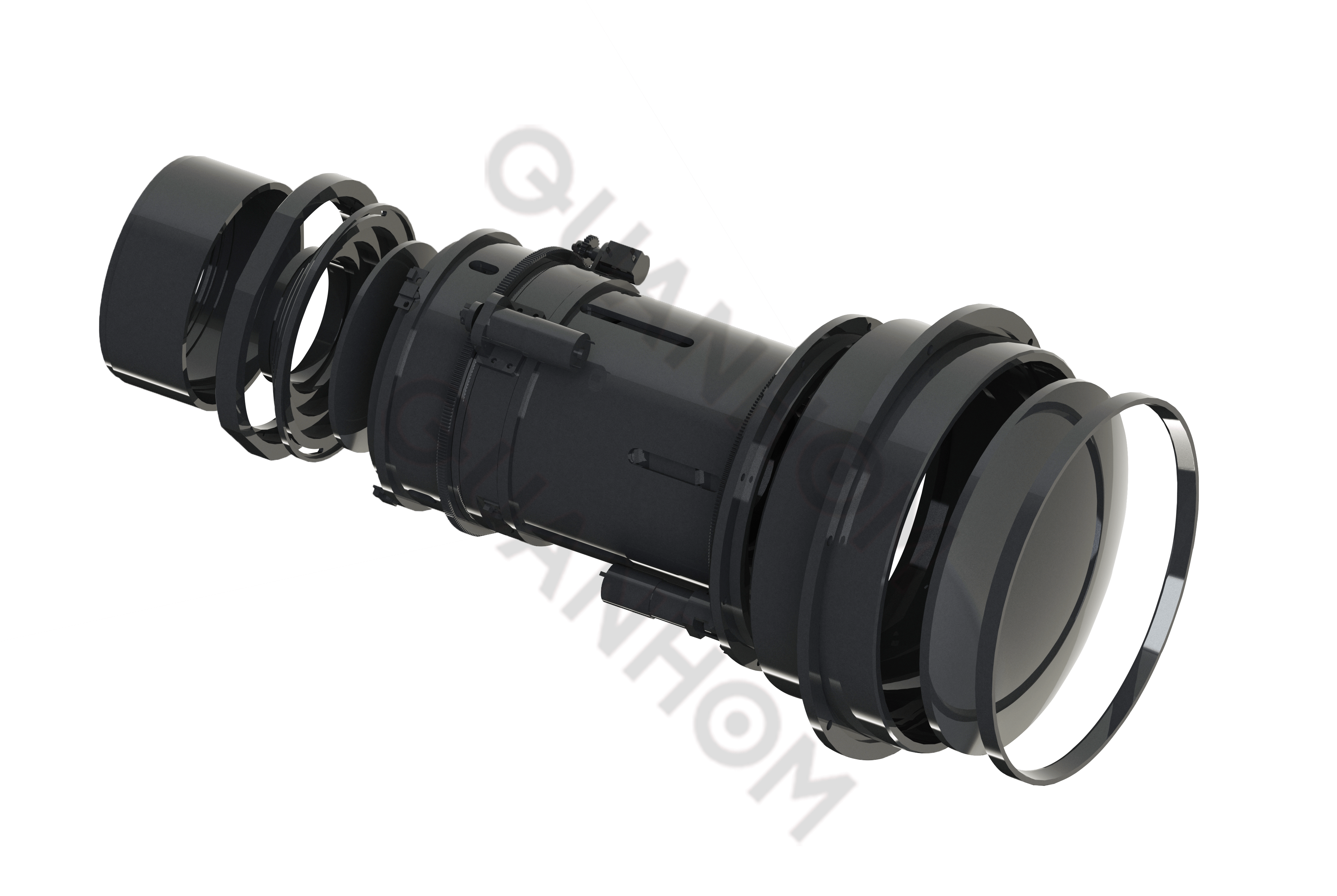
Optical Structure
The optical structure of a mechanically compensated zoom lens consists of a front fixed group, a zoom group, a compensation group, and a rear fixed group.
1. Front fixed group: its function is to provide a fixed image to the system;
2. Zoom group: it is responsible for the zoom function of the system and moves linearly to change the focal length;
3. Compensation group: make non-linear movement according to a certain curve track to compensate the image surface movement caused by the zoom group in the process of zooming;
4. Post-fixed group: used to convert the image of the compensation group into the final real image of the system, and adjust the composite focal length of the system and the device aperture diaphragm to ensure that the relative aperture of the system remains unchanged during the zoom movement.
Continuous Zoom Mechanism
It’s mainly composed of motor, gear, zoom cam, limit device, guide pin, zoom group, compensation group, guide mechanism, etc. Among them, the design of the guide mechanism and zoom cam is the core technology of continuous zoom mechanism. The working principle is: when the product needs to zoom, the control system sends the motor zoom signal, the motor drives the gear, and the gear drives the zoom cam to move. At this time, the zoom group and the compensation group meet the functional relationship through the guide pin The movement is carried out in the two cam grooves to realize the linear movement of the zoom group and the compensation group. When the zoom group and the compensation group move to the two extreme positions, the pressure switch is used to control the work of the drive motor. The precision potentiometer is driven by the gear to rotate with the zoom cam, and the potentiometer outputs different voltages with the angle of the zoom cam. The corresponding focal length of the system can be obtained by converting the voltage value.
1. The guide mechanism of the zoom group
(1) A combination mechanism of a smooth guide rail and a ball screw. This kind of structure has high precision. Due to the different trajectories of simultaneous movement of zooming and compensation, two sets of guiding drive mechanisms are required, occupying a large space, and designing the control system is also difficult.
(2) Two cylindrical guide rail sliding mechanism. Since the sliding part is two cylindrical guide rails, this structure has high zoom accuracy and carries a larger load than the first one. However, due to the superpositioning structure, the optical aperture is too large, which is prone to mechanism jamming, and the radial size of the mechanism is also relatively large. Generally suitable for structures with a light aperture of 30-80 mm.
(3) Three cylindrical guide rail sliding mechanism. The advantage of this structure is that it is comfortable and stable in movement, not prone to jamming, and can drive optical components with larger apertures. The disadvantage is that the movement accuracy is lower than the previous two, and it is generally suitable for structures with a clear aperture of 50-120mm.
2. Design of zoom cam
Cam mechanism function: realizes the actuator that converts the motor's rotary motion into a variable magnification and compensates the translational movement of the mirror group along the optical axis.
When designing a variable-magnification cam, it should be noted that the friction coefficient of the guide pin and the cam groove is closely related to the self-locking angle. The larger the friction coefficient, the smaller the self-locking angle, and the flatter the cam groove is. The curve design of the cam groove is particularly important.
Quanhom Technology Co., LTD is a company engaged in the development, manufacturing, and offering customization services of wide range of opto-mechatronics components. Our teams bridge the gap between excellent performance and limited budget, remarkably we've been involved in projects those integrated high precision product includes infrared optical assemblies of VIS/SWIR/MWIR/LWIR, eyepieces, infrared lens elements (from single FOV to fast switching multiple FOV and continuous zooming infrared lens) and more around the globe.